Not logged in

List of Design Forms calculations:

▶ EuroCode - EN 1993-1-1
Check N+My+Mz
EuroCode - EN 1993-1-1 -
Author: Design Forms s.r.o.
Created: 6/9/2016
Last updated: 10/13/2016
Description:
Check steel section for N+My+Mz
Annotation:


Table B.3 - Coefficients Cm equivalent of constant moment


Check bending with LTB
EuroCode - EN 1993-1-1 -
Author: Design Forms s.r.o.
Created: 6/27/2016
Last updated: 8/29/2016
Description:
Check of bending with lateral torsional buckling
Annotation:


Image NB 3.1. - Values description and symbol convention during loading by Fz


(C) - compression fibers, (T) - tension fibers, S - shear center, G - center of gravity


Image NB 3.2. - Symetric cross sections - symetric to center or to the stiff axis


Table NB 3.1. - Coefficient values C1 and C3 when member is loaded by end moments dependent on  coefficients kz and coefficients yf and kwt


remark 1)

remark 2) 0,7L = fixed left end, 0,7R = fixed right end


Table NB 3.2. - Coefficient values C1, C2 and C3 for different cases of perpendicular loading, dependend on coefficients ky, kz, kw and coefficients yf and kwt


remark 1)

remark 2) Parameter ψf is for the center of the length

remark 3) Values of critical moment Mcr is for the section with Mmax


Check of member buckling
EuroCode - EN 1993-1-1 -
Author: Design Forms s.r.o.
Created: 6/27/2016
Last updated: 8/29/2016
Description:
Check member buckling
Annotation:

Table 6.1. - Coefficients of imperfections on buckling curvatures


Curvature of buckling strength a0 a b c d
Coefficients of imperfection a 0,13 0,21 0,34 0,49 0,76


Image 6.4 - Curvature of buckling strength


χ - Buckling coefficient

λ - Slenderness ratio


Table 6.2 - Assignment of curvatures of buckling strengths to cross sections


Check of circle rivet
EuroCode - EN 1993-1-1 -
Author: Design Forms s.r.o.
Created: 7/7/2016
Last updated: 8/29/2016
Description:
Check of circle rivet
Annotation:


Table 3.9 - Geometric requirements on members which ends by rivet connections


A - the thickness t is defined

B - the geometry is defined


Image 3.11 - Rivet geometry


Check of high strength bolts
EuroCode - EN 1993-1-1 -
Author: Design Forms s.r.o.
Created: 7/7/2016
Last updated: 8/29/2016
Description:
Check high strength bolts
Annotation:

Table 3.6 - Values of "ks"


Description ks
Bolts in general openings 1,00
Bolts in bigger openings or short longer openings where axis of an opening is perpendicular on the load 0,85
Bolts in long longer openings where axis of an openings is perpendicular to load 0,70
Bolts in short longer openings where axis of an opening is parallel on the load 0,76
Bolts in long longer openings where axis of an openings is parallel to load 0,63


Table 3.7 - Coefficient of friction m for pre-stressed bolts


Surface friction class (see related codes 1.2.7; group 7) m
Blasted surface without rust; or blasted surface with aluminium of zinc coat 0,50
Blasted surface with alkalic-zinc-silicate coat - thickness 50-80 mm 0,40
Surface cleaned by brush or flame 0,30
Without modifications 0,20

Check of shear
EuroCode - EN 1993-1-1 -
Author: Design Forms s.r.o.
Created: 7/7/2016
Last updated: 8/29/2016
Description:
Check of shear
Annotation:
Check of shear

Check of shear and bending
EuroCode - EN 1993-1-1 -
Author: Design Forms s.r.o.
Created: 7/7/2016
Last updated: 8/29/2016
Description:
Check of shear and bending moment
Annotation:
Check of shear and bending

Check of simple bending
EuroCode - EN 1993-1-1 -
Author: Design Forms s.r.o.
Created: 7/7/2016
Last updated: 8/29/2016
Description:
Check of simple bending
Annotation:
Check of simple bending

Check of simple compression
EuroCode - EN 1993-1-1 -
Author: Design Forms s.r.o.
Created: 7/7/2016
Last updated: 8/29/2016
Description:
Check steel section in simple compression
Annotation:
Check of simple compression

Check of simple tension
EuroCode - EN 1993-1-1 -
Author: Design Forms s.r.o.
Created: 7/7/2016
Last updated: 8/29/2016
Description:
Check of simple tension
Annotation:
Check of simple tension

Check welds
EuroCode - EN 1993-1-1 -
Author: Design Forms s.r.o.
Created: 10/10/2016
Last updated: 11/15/2016
Description:
Check welds
Annotation:
Check welds

▶ EuroCode - EN 1992-1-1
Calculation of the anchor length
EuroCode - EN 1992-1-1 -
Author: Design Forms s.r.o.
Created: 7/20/2016
Last updated: 9/27/2016
Description:
Calculation of the anchoring length of the reinforcement
Annotation:

Image 8.1 - Other ways of anchors then straight anchors


a) basic tensile anchor length lb, measured on center line for all shapes

b) equivalent anchor length for standard bend

c) equivalent anchor length for standard hook

d) equivalent anchor length for standard loop

e) equivalent anchor length for bar welded perpendicullar


8.4.2 Limit stress in cohesion


(1)P The ultimate bond stress shall be such that there is an adequate safety margin against bond failure.

(2) The design value of the ultimate bond stress, fbd, for ribbed bars may be taken as:


fbd = 2,25 * η1 * η2 * fctd

where fctd is design value of concrete tensile strength according to 3.1.6(2)P. Due to the increasing brittleness of higher strength concrete, fctk,0,05 should be limited here to the value for C55, unless it can be verified that the average bond strength increases above this limit

η1 coefficient related to the quality of the bond condition and the position of the bar during concreting

   (see Figure 8.2):

   η1 = 1,0 when ‘good’ conditions are obtained and

   η1 = 0,7 for all other cases and for bars in structural elements built with slip-forms, unless it can be shown that ‘good’ bond conditions exist

η2 is related to the bar diameter: η2 = 1,0 for φ ≤ 32 mm η2 = (132 - φ)/100 for φ > 32 mm


Image 8.2 - Description of cohesion conditions


[A] - concreting direction

a) and b) ‘good’ conditions of cohesion for all bars

c) and d) not-hatched area - ‘good’ conditions of cohesion; hatched area - ‘bad’ conditions of cohesion


Table 8.2 - Coefficient values fora1, a2, a3, a4, a5


Influencing factor Type of anchorage reinf. bar in tension reinf. bar in compression
Shape of bars Straight

Other than straight

(see Figure 8.1 (b),(c) and (d))
α1 = 1,0

α1 = 0,7 if cd>3*ϕ

otherwise α1 = 1,0(see Fig. 8.4 for values of cd)
α1 = 1,0

α1 = 1,0
Concrete cover Straight

Other than straight

(see Figure 8.1 (b),(c) and (d))
α2 = 1 – 0,15 (cd – φ)/φ; ≥ 0,7; ≤ 1,0

α2 = 1 – 0,15 (cd – 3φ)/φ; ≥ 0,7; ≤ 1,0; (see Fig. 8.4 for values of cd)
α2 = 1,0

α2 = 1,0
Confinement by transverse reinforcement

not welded to main reinforcement
All types α3 = 1 – K*λ; ≥ 0,7; ≤ 1,0 α3 = 1,0
Confinement by welded transverse reinforcement* All types, position and size as specified in Figure 8.1 (e) α4 = 0,7 α4 = 0,7
Confinement by transverse pressure All types α5 = 1 – 0,04p; ≥ 0,7; ≤ 1,0 -

where: λ = (ΣAst - ΣAst,min)/ As

ΣAst cross-sectional area of the transverse reinforcement along the design anchorage length lbd

ΣAst,min cross-sectional area of the minimum transverse reinforcement = 0,25 As for beams and 0 for slabs

As area of a single anchored bar with maximum bar diameter K values shown in Figure 8.3

p transverse pressure [MPa] at ultimate limit state along lbd

* See also 8.6: For direct supports lbd may be taken less than lb,min provided that there is at least one transverse wire welded within the support. This should be at least 15 mm from the face of the support. 


Concrete cover
EuroCode - EN 1992-1-1 -
Author: Design Forms s.r.o.
Created: 7/20/2016
Last updated: 8/29/2016
Description:
Calculation of cover of the reinforcement
Annotation:


Value Dcdev, which should be used is in the national annex. The recommended value is 10 mm.


Value Dcdur,st, kwhich should be used is in the national annex. The recommended value without any other specification is 0 mm.


Value Dcdur,g, which should be used is in the national annex. The recommended value is 0 mm.


Value Dcdur,add, which should be used is in the national annex. The recommended value without any other specification is 0 mm.


Table 4.1 – Enviroment effect degree according to EN 206-1


Table 4.3 – Recommended modification of the construction classification


Table 4.4 – Min concrete cover cmin,dur required due to durability of reinforcement according to EN 10080


Table 4.5N – Min concrete covercmin,dur required due to durability of reinforcement


Check shear reinforcement
EuroCode - EN 1992-1-1 -
Author: Design Forms s.r.o.
Created: 7/25/2016
Last updated: 8/29/2016
Description:
Check of shear reinforcement
Annotation:

NP 45: Values CRd,c, vmin and k1, which are used in state may be found in national annex.


Recommended value for CRd,c is 0,18 / gc, for vmin is defined by formuls(6.3N) and for k1 is 0,15.


NP 47: Limit values cot q, which are used in state may be found in national annex. Recommended limitations are defined by formula 1 < cotq q < 2,5.


Coefficient aI (equation 6.4):


  • aI = lx/lpt2 < 1,0 for the prestressed reinforcement

  • aI = 1,0 for other kinds of prestressing;


Check longitudinal reinforcement
EuroCode - EN 1992-1-1 -
Author: Design Forms s.r.o.
Created: 7/25/2016
Last updated: 8/29/2016
Description:
Check of longitudinal reinforcement
Annotation:

Design compression and tension strength


(1)P Design concrete compression strength is defined by formula (3.15)


where γis partial factor of conctrete, see 2.4.2.4;


          αcc coefficient taking account of long term effects on the compressive strength


remark - αcc is defined by national annex, it maybe 0,8 - 1,0, recommended value is 1 (NP12)


(2)P Design concrete tension strenght is defined by formula (3.16)


where γc is partial factor of conctrete, see 2.4.2.4;

          αct coefficient taking account of long term effects on the tensile strength


remark - value αct is defined by national annex, recommended value is 1 (NP13)


Interaction diagram
EuroCode - EN 1992-1-1 -
Author: Design Forms s.r.o.
Created: 8/26/2016
Last updated: 8/29/2016
Description:
Interaction diagram of concrete section (N-My)
Annotation:
Interaction diagram

Check reinforcement ratio of concrete cross section
EuroCode - EN 1992-1-1 -
Author: Design Forms s.r.o.
Created: 8/29/2016
Last updated: 8/29/2016
Description:
Check reinforcement ratio of concrete cross section
Annotation:
Check reinforcement ratio of concrete cross section

Check response
EuroCode - EN 1992-1-1 -
Author: Design Forms s.r.o.
Created: 10/19/2016
Last updated: 10/19/2016
Description:
Check response of concrete cross section
Annotation:
Calculates and draws stress-strain response of the concrete cross section.

Calculation of crack width
EuroCode - EN 1992-1-1 -
Author: Design Forms s.r.o.
Created: 10/20/2016
Last updated: 10/20/2016
Description:
Calculation of crack width
Annotation:


  Stress in the reinforcement ss1 may be defined by calculation from bending moment MEd


or it can be set manually (when MEd = 0).


And p‘ is area beforehand of afterwards stressed reinforcement in area Ac,eff

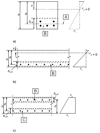
Ac,eff effective area of tension concrete surrounded by reinforcement of prestressed reinforcement in height hc,ef  (see image 7.1)


hc,ef is smaller from:


  • 2,5(h - d)

  • (h - x)/3

  • h/2


Image 7.1 - Effective tension area (typical cases)


a) beam

b) plate

c) member in tension

[A] - center of gravity of reinforcement

[B] - effective tension area, Ac,eff

[C] - effective tension area near top suface, Acb,eff
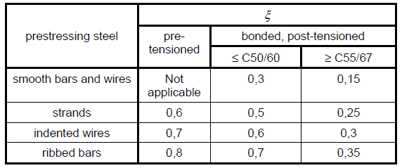


is ration of strength of prestressed reinforcement and reinforcement according to the table 6.2 in 6.8.2:


k1 is coefficient of coherent parameters of reinforcement:

= 0,8 bars with big cohesion;

= 1,6 bars with smooth surface (e.g. presstresing bars);


k2 is coefficient of ratio of deformation :

= 0,5 for bending;

= 1,0 for simple tension.

In cases of eccentric tension or local areas - the values k2should be used, it is calculated by this formula:

k2 = (e1 + e2)/2e1

where e1 is bigger ande2 is smaller tension deformation ratio on edges of cross section, which is weakened by crack.


Values k3 and k4, which are used may be found in the nationa annex. The recommended values in Czech Republic (see NA 2.74):


k3 = 3,400


k4 = 0,425.


Table 7.1N - Recommended values wmax (mm)


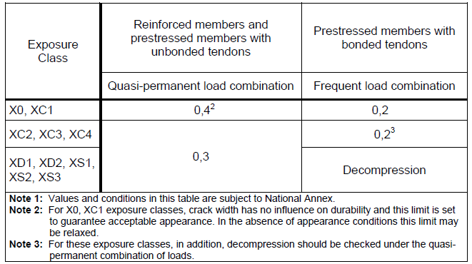
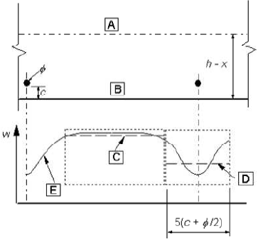
Image 7.2 - The crack on the concrete surface dependent on the distance from the bar


[A] - neutral axis

[B] - surface of tensioned concrete

[C] - expected crack width according to (7.14)

[D] - expected crack width according to (7.11)

[E] - real crack width


Internal forces on the cracking limit
EuroCode - EN 1992-1-1 -
Author: Design Forms s.r.o.
Created: 11/2/2016
Last updated: 11/2/2016
Description:
Calculation of combination on the cracking limit
Annotation:

Template calculates combination of internal forces which causes limit tensional stress in the concrete.


Template takes input combination of  internal forces { N, My, Mz } and iterates coefficient "R" to obtain new combination {N, R*My, R*Mz} which causes limit tensional stress in the concrete.


It means that normal force is not changed, it remains. Bending moments are modified to obtain limit stress.


Check long and shear reinforcement
EuroCode - EN 1992-1-1 -
Author: Design Forms s.r.o.
Created: 11/9/2016
Last updated: 11/9/2016
Description:
Check long and shear reinforcement
Annotation:
Check longitudinal and shear reinforcement on general cross section.

▶ EuroCode - EN 1995-1-1
Check buckling
EuroCode - EN 1995-1-1 -
Author: Design Forms s.r.o.
Created: 8/19/2016
Last updated: 8/29/2016
Description:
Check timber member buckling
Annotation:

Value of coefficients bc should be according this (paragraph 6.3.2):


Material bc
Solid timber 0,20
Glued timber and LVL 0,10


Value of coefficients km should be considered according to (paragraph 6.1.6):


Material Cross section km
Solid timber, glued timber, LVL rectangle cross sections 0,70
other cross sections 1,00
other conxtruction members based on timber all cross sections 1,00


Table 6.1 - Effective length as distance ratio


Check combination N+My+Mz
EuroCode - EN 1995-1-1 -
Author: Design Forms s.r.o.
Created: 8/19/2016
Last updated: 8/29/2016
Description:
Check timber member on combination N+My+Mz
Annotation:

Value of coefficients bc should be according this (paragraph 6.3.2):


Material bc
Solid timber 0,20
Glued timber and LVL 0,10


Value of coefficients km should be considered according to (paragraph 6.1.6):


Material Cross section km
Solid timber, glued timber, LVL rectangle cross sections 0,70
other cross sections 1,00
other conxtruction members based on timber all cross sections 1,00


Table 6.1 - Effective length as distance ratio


Check tension
EuroCode - EN 1995-1-1 -
Author: Design Forms s.r.o.
Created: 8/19/2016
Last updated: 8/29/2016
Description:
Check timber member on tension
Annotation:

Anet - net area of cross section (without bolt holes, slots, etc.)


Value coefficients bc should be considered according to(paragraph 6.3.2):


Material bc
Solid timber 0,20
Glued timber and LVL 0,10

Connection timber-steel
EuroCode - EN 1995-1-1 -
Author: Design Forms s.r.o.
Created: 8/19/2016
Last updated: 11/7/2016
Description:
Check of connection timber-steel
Annotation:


Image 8.3 - Kind of breaches for connection steel - timber


Image 8.4 - Definition t1, t2


a) on shear plane; b) two shear planes


Image 8.5 - Covering nails


Image 8.7 - Distances from ends and edges


a) distances paraller with grain in the line and paraller to grain between lines; b) distances from ends and edges


(1) - loaded end

(2) - un-loaded end

(3) - loaded edge

(4) - un-loaded edge

1 - connection

2 - fibers direction


▶ Invariant - Statics
Statics of simple beam
Invariant - Statics -
Author: Design Forms s.r.o.
Created: 8/20/2016
Last updated: 8/29/2016
Description:
Bending moment and shear force on simple beam
Annotation:
Bending moment and shear force on simple beam

Statics of console
Invariant - Statics -
Author: Design Forms s.r.o.
Created: 8/29/2016
Last updated: 8/29/2016
Description:
Statics of console
Annotation:
Statics of console

General cross section parameter
Invariant - Statics -
Author: Design Forms s.r.o.
Created: 9/19/2016
Last updated: 9/19/2016
Description:
Calculate parameters of general cross section
Annotation:
Calculate parameters of general cross section

▶ EuroCode - EN 1996-1-1
Check of masonry in compression
EuroCode - EN 1996-1-1 -
Author: Design Forms s.r.o.
Created: 8/23/2016
Last updated: 8/29/2016
Description:
Check of masonry in compression
Annotation:
Check of masonry in compression

Check of masonry in concentric compression
EuroCode - EN 1996-1-1 -
Author: Design Forms s.r.o.
Created: 8/23/2016
Last updated: 8/29/2016
Description:
Check of masonry in concentrated compression
Annotation:
Check of masonry in concentrated compression

Check of masonry loaded by lateral force
EuroCode - EN 1996-1-1 -
Author: Design Forms s.r.o.
Created: 8/24/2016
Last updated: 8/29/2016
Description:
Check of masonry loaded by lateral force
Annotation:
Check of masonry loaded by lateral force

▶ EuroCode - EN 1997-1-1
Geostatic stress
EuroCode - EN 1997-1-1 -
Author: Design Forms s.r.o.
Created: 9/19/2016
Last updated: 9/19/2016
Description:
Calculation of geotechnic stress
Annotation:
Calculation of geotechnic stress

Bearing capacity of bored piles according ULS
EuroCode - EN 1997-1-1 -
Author: Design Forms s.r.o.
Created: 9/22/2016
Last updated: 9/22/2016
Description:
Bearing capacity of bored piles according to Masopust theory (ČSN 73 1002)
Annotation:
Bearing capacity of bored piles according to Masopust theory (ČSN 73 1002)

Bearing capacity of group of piles
EuroCode - EN 1997-1-1 -
Author: Design Forms s.r.o.
Created: 9/22/2016
Last updated: 9/22/2016
Description:
Bearing capacity of pile group according to the Masopust theory (ČSN 73 1002)
Annotation:
Bearing capacity of pile group according to the Masopust theory (ČSN 73 1002)

Bearing capacity of single micropile
EuroCode - EN 1997-1-1 -
Author: Design Forms s.r.o.
Created: 9/26/2016
Last updated: 7/31/2017
Description:
Bearing capacity of single micropile
Annotation:
Bearing capacity of single micropile

Check bearing capacity of pad foundation
EuroCode - EN 1997-1-1 -
Author: Design Forms s.r.o.
Created: 11/7/2016
Last updated: 11/9/2016
Description:
Check bearing capacity of pad foundation
Annotation:

Check bearing capacity of pad foundation.


Checks:


  • Check drained bearing capacity

  • Check drained sliding resistance

  • Check undrained bearing capacity

  • Check undrained sliding resistance


Check stability of gravity wall
EuroCode - EN 1997-1-1 -
Author: Design Forms s.r.o.
Created: 12/5/2016
Last updated: 12/5/2016
Description:
Check stability of gravity wall
Annotation:

Calculation of earth pressure coefficients and earth pressures


  • Horizontal earth pressure coefficients are calculated according to EN 1997-1 Annex C 2. By using this method, it is possible to calculate coefficients of horizontal active and passive earth pressure for variable soil conditions, terrain inclination, construction inclination and soil strength parameters.

    • Partial coefficient of horizontal earth pressure for vertical loading on the surface:


(1)


    • Partial coefficient of horizontal earth pressure for cohesion


(2)


    • Partial coefficient of horizontal earth pressure for soil weight 


(3)


  • In the formulas (1) - (3), b is the angle from the horizontal to the soil surface (positive when the soil surface rises away from the wall),Q is the angle between the vertical and the wall direction (positive when the soil overhangs the wall), f is the angle of internal friction and KN is the coefficient of the normal earth pressure acting on the wall from a unit pressure normal to the surface. Further detail can be found in EN 1997-1 Annex C 2.


  • The inclusion of the mobilisation of earth pressure in front of the wall is optional. Height of the soil in front of the wall hp is an input parameter. User has 2 possible alternatives:

    • No earth pressure in front of the wall is taken into account,


    • 1/2 passive earth pressure + 1/2 earth pressure at rest 


Check wall stability


  • Degree of utilization in the case of toppling is calculated according to the formula (5), where MED,dst and MED,stb are destabilizing and stabilizing moment around the construction toe. 


(5)

Safety factors according to EN 1997


  • It is possible to use 9 different partial factors:

    • gG- partial factor of safety for the unfavorable permanent  load (Action),

    • gG,fav- partial factor of safety for the favorable permanent  load (Action),

    • gload - partial factor of safety for the surface load - for higher versatility treated as separate factor (Action),

    • gRh- partial factor of safety for sliding resistance (Resistance),

    • gRv- partial factor of safety for bearing resistance (Resistance),

    • gangle- partial factor of safety for the angle of internal friction (Material),

    • gcohesion- partial factor of safety for the cohesion (Material),

    • gweight,soil- partial factor of safety for the soil unit weight (Material), 

    • gweight,wall- partial factor of safety for the wall unit weight (Material).


  • Appropriate combination of partial factors can be chosen for required design approach.

  • Earth pressure in front of the wall is taken as favorable action.


Bearing capacity of strand anchors
EuroCode - EN 1997-1-1 -
Author: Design Forms s.r.o.
Created: 12/13/2016
Last updated: 12/13/2016
Description:
Bearing capacity of strand anchors
Annotation:

Anchor parameters


Type of strand 15,5/1620 15,5/1800 15,7/1770
Nominal diameter [mm] 15,5 15,5 15,7
Nominal Cross-section [mm2] 141,5 141,5 150,0
Forces and stresses
at limit strength Fm [kN] 229,2 255 265,5
fp [MPa] 1620 1800 1770
at limit 0,2 Fp0,2 [kN] 194,8 217 235,5
fp0,2 [MPa] 1377 1532 1570
at limit 0,1 Fp0,1 [kN] - 178 -
fp0,1 [MPa] - 1620 -
Ductility [%] 3,0 3,5 3,5
Elastic modulus [GPa] 200 ± 10 % 200 ± 10 % 195
Nominal weight [kg] 1,12 1,12 1,15
Nominal bearing capacity [kN] 120 140 142


Bearing capacity of bar anchors
EuroCode - EN 1997-1-1 -
Author: Design Forms s.r.o.
Created: 12/15/2016
Last updated: 12/15/2016
Description:
Bearing capacity of bar anchors
Annotation:

Anchor parameters


Anchor parameters are obtained from manufacturer's table


Anchor parameter Anchor

CPS
Anchor Dywidag
Steel 835/1030 Steel 1080/1230
Ø32 Ø26,5 Ø32 Ø36 Ø26,5 Ø32 Ø36
Nominal diameter [mm] 32 26,5 32 36 26,5 32 36
Screw pitch [mm] 17 13 16 18 13 16 18
Cross-section area [mm2] 777 551 804 1018 551 804 1018
Weight [kg/m] 6,78 4,48 6,53 8,27 4,48 6,53 8,27
Ultimate strength [kN] 776 568 828 1049 678 989 1252
Stress at ultimate strength [MPa] 1000 1030 1230
Limit anchor force [kN] 415 284 414 524 339 495 626

▶ EuroCode - EN 1991
Wind load
EuroCode - EN 1991 - Wind
Author: Design Forms s.r.o.
Created: 1/10/2017
Last updated: 2/22/2017
Description:
Basic wind speed and pressure
Annotation:

Dialogue


National annex selector


Combobox "National Annex" is used for selecting proper annex for calculation of the wind load.

Wind load requires selection the national annex, because in Standard EN is many national decisions possible.

For explanation of the National annex parameters related to wind load select national annex from the list below.

BS National Annex


ČSN National Annex


DIN National Annex


ELOT National Annex


IS National Annex


LU National Annex


NBN National Annex


NEN National Annex


NF National Annex


ÖNORM National Annex


PN National Annex


SFS National Annex


SIST National Annex


SR National Annex


STN National Annex


General properties


General properties are similar to all wind load forms.

Checkbox "Print headline" represent official name for calculation. User can change it by uncheck "Print headline" and check "Print user defined headline" and write his own headline into appropriate string line.

Wind parameters


This group of parameters depend on selected national annex.

BS National Annex


Wind azimuth in degrees is used in calculation of directional factor cdir. Wind azimuth is from 0 ° to 360 ° from North in a clockwise direction.

Fundamental value of the basic wind velocity from the map vb,map in metres per second. Map can be found in National annex page, Figure NA.1

Turbulence intensity from the diagram Iv(z)map. Diagram can be found in National annex page, Figure NA.5

Turbulence intensity factor from the diagram kI,T. Diagram can be found in National annex page, Figure NA.6

CSN National Annex


Wind region is from I to V according map of the wind regions. Map can be found in National annex page.

DIN National Annex


Wind region is from WZ1 to WZ4 according map of the wind regions. Map can be found in National annex page.

ELOT National Annex


No special wind parameters are necessary for ELOT National annex.

IS National Annex


Wind azimuth in degrees is used in calculation of directional factor cdir. Wind azimuth is from 0 ° to 360 ° from North in a clockwise direction.

Fundamental value of the basic wind velocity from the map vb,map in metres per second. Map can be found in National annex page, Figure NA.1

Turbulence intensity from the diagram Iv(z)map. Diagram can be found in National annex page, Figure NA.5

Turbulence intensity factor from the diagram kI,T. Diagram can be found in National annex page, Figure NA.6

LU National Annex


No special wind parameters are necessary for LU National annex.

NBN National Annex


Wind region is from 1 to 4 according map of the wind regions. Map can be found in National annex page.

Wind azimuth in degrees is used in calculation of directional factor cdir. Wind azimuth is from 0 ° to 360 ° from North in a clockwise direction.

NEN National Annex


Wind region is from I to III according map of the wind regions. Map can be found in National annex page.

NF National Annex


Wind region is from 1 to 4 according map of the wind regions. Map can be found in National annex page.

Direction zone is from 1 to 3 according map of the wind directions. Map can be found in National annex page.

Wind azimuth in degrees is used in calculation of directional factor cdir. Wind azimuth is from 0 ° to 360 ° from North in a clockwise direction.

ONORM National Annex


According selected state in Austria can be selected the municipality which is the nearest to the construction site. Table of all possible municipalities can be found in National annex page.

PN National Annex


Wind region is from 1 to 3 according map of the wind regions. Map can be found in National annex page.

Wind azimuth in degrees is used in calculation of directional factor cdir. Wind azimuth is from 0 ° to 360 ° from North in a clockwise direction.

SFS National Annex


Wind regions in SFS are defined as:

a) Mainland in the entire country

b) Sea areas: open sea, scattered islands out in the open sea

c) In Lappland: at the top of mountains

d) In Lappland: at the bottom of mountains

SIST National Annex


Wind region is from 1 to 3 according map of the wind regions. Map can be found in National annex page.

SR National Annex


Fundamental value of the basic wind velocity from the map in metres per second. Map can be found in National annex page.

STN National Annex


Wind region is from I to II according map of the wind regions. Map can be found in National annex page. For higher altitude, two more regions are available.

Terrain parameters


Standard values exist. Different parameters can be defined in National annex.

Standard values


Terrain category is standardly from 0 to IV. Different terrain categories can be defined in National annex page.

Checkbox "Calculate orographic factor" allows calculation of orographic factor. In National annex can be specified procedure to calculate orographic factor. Standard procedure is in Annex A.3.

BS and IS National Annexes


Three terrain categories are available in BS. Sea, Country and town. More information about BS terrain categories can be found in National annex page.

Roughness factor cr,diag is determined from the diagram Figure NA.3 Diagram can be found in National annex page.

Roughness correction factor cr,T is determined from the diagram Figure NA.4 Diagram can be found in National annex page.

Exposure factor ce,diag is determined from the diagram Figure NA.7 Diagram can be found in National annex page.

Exposure correction factor ce,T is determined from the diagram Figure NA.8 Diagram can be found in National annex page.

Distance upwind to shoreline in km is used in the diagrams mentioned above.

Distance inside town terrain in km is used in the diagrams mentioned above.

Checkbox "Calculate orographic factor" is used, if orographic factor should be calculated according Annex A.3

Orographic factor - Recommended Annex A.3 input


Orographic terrain can be Cliffs and escarpments or Hills and ridges.

Horizontal distance of the site from the top of the crest in metres. Use positive value for downwind slope and negative value for upwind slope.

Effective height of the hill in metres.

Actual length of the upwind slope in the wind direction in metres.

Actual length of the downwind slope in the wind direction in metres.

Construction parameters


Construction parameters depend on selected National annex.

Reference height above terrain in metres is the most important parameter. It define in which height is calculated wind pressure. If is necessary to calculate wind pressure in more heights, repeat calculation with propper height z.

Checkbox "Temporary structure or execution phase" is used, if season construction is designed and season factor is necessary.

Checkbox "Use accurate information about the obstructions height" is used, if average height of neighbouring structures is know in Terrain category IV.

Calculation


Basic values


Basic wind velocity is calculated as vb = cdir • cseason • vb,0 in metres per second.

Fundamental value of the basic wind velocity vb,0 is defined in selected National annex in metres per second. 

Directional factor cdir = 1.0 in standard. Different value can be defined in National annex page.

Season factor cseason = 1,0 in standard. A different value can be defined in National annex page.

Reference height above terrain in metres is the height in which is peak velocity pressure calculated. It is one of the most important values in the calculation.

Mean wind velocity


For DIN and ONORM are this and follows paragraphs unavailable. Instead of it, there is block "Wind parameters" where is calculation of wind parameters according National annex.

Mean wind velocity in metres per second is calculated as vm = cr • cO • vb

Terrain roughness factor cr depends on height above ground level and selected terrain category.

 for zmin ≤ z ≤ zmax

 for z ≤ zmin

where:

z0 is the roughness length

kr is terrain factor


where:

z0,II = 0,05 (terrain category II, Table 4.1)

zmin is the minimum height defined in Table 4.1

zmax is to be taken as 200 m


Table 4.1 - Terrain categories and terrain parameters


Terrain category z0

[m]
zmin

[m]
0   Sea or coastal area exposed to the open sea 0,003 1
I   Lakes or flat and horizontal area with negligible vegetation and without obstacles 0,01 1
II   Area with low vegetation such as grass and isolated obstacles (trees, buildings) with separations of at least 20 obstacle heights 0,05 2
III   Area with regular cover of vegetation or buildings or with isolated obstacles with separations of maximum 20 obstacle heights (such as villages, suburban terrain, permanent forest) 0,3 5
IV   Area in which at least 15 % of the surface is covered with buildings and their average height exceeds 15 m 1,0 10


Orography factor cO = 1 in normal cases.

Where orography increases wind velocities by more than 5 % the effects should be taken into account using the orography factor. Recommended procedure is given in Annex A.3. Different procedure can be specified in National annex.

Orographic factor - Recommended procedure according to Annex A.3


1) Calculation of the upstream slope


2) Decision if the calculation of orography factor is necessary

The effects of orography should be taken into account in the following situations:

a) For sites on upwind slopes of hills and ridges:

- where 0,05 < Φ ≤ 0,3 and |x| ≤ Lu / 2

b) For sites on downwind slopes of hills and ridges:

- where Φ < 0,3 and x < Ld / 2

- where Φ ≥ 0,3 and x < 1,6 • H

c) For sites on upwind slopes of cliffs and escarpments:

- where 0,05 < Φ ≤ 0,3 and |x| ≤ Lu / 2

d) For sites on downwind slopes of cliffs and escarpments:

- where Φ < 0,3 and x < 1,5 • Le

- where Φ ≥ 0,3 and x < 5 • H


3) Orography factor is than defined by:


Orographic factor Limits
cO = 1 Φ < 0,05
cO = 1 + 2 • s • Φ 0,05 < Φ < 0,3
cO = 1 + 0,6 • s Φ > 0,3

where:

s is the orographic location factor

Φ is the upwind slope H/Lu in the wind direction

Le is the effective length of the upwind slope

Lu is the actual length of the upwind slope in the wind direction

Ld is the actual length of the downwind slope in the wind direction

H is the effective height of the feature

x is the horizontal distance of the site from the top of the crest

z is the vertical distance from the ground level of the site


Values of the effective length Le


Type of slope (Φ = H/Lu)
Shallow (0,05 < Φ < 0,3) Steep (Φ > 0,3)
Le = Lu Le = H/0,3


Orographic location factor s for cliffs and escarpments


Orographic location factor s for hills and ridges


a) upwind section for all orography

For the ranges


take


where


when


take

s = 0

b) downwind section for cliffs and escarpments

For the ranges


take


where


For the range


interpolate between values for


when


use the values for


when


take

s = 0

c) downwind section for hills and ridges

For the ranges


take


where


when


take

s = 0

Displacement height - Recommended procedure according Annex A.5


For building in Terrain category IV, can be reference height of building on the upwind side lowered by displacement height hdis due to closely spaced buildings and other obstructions.


hdis = min(0,8 • have; 0,6 • h) for x ≤ 2 • have

hdis = min(1,2 • have - 0,2 • x; 0,6 • h) for 2 • have ≤ x ≤ 6 • have

hdis = 0 for x ≥ 6 • have

Peak velocity pressure


Function for calculation peak velocity pressure at height z can be defined in National annex. Recommended formula is:


where:

ρ is the air density, which depends on the altitude, temperature and barometric pressure. ρ can be defined in National annex, recommended value is 1,25 kg/m3.

vm is mean wind velocity

Iv is turbulence intensity. It can be defined in National annex. Recommended formula is:

 for zmin ≤ z ≤ zmax

Iv = Iv(zmin) for z ≤ zmin

kI is turbulence factor. It may be defined in National annex. Recommended value is 1,0

Explanation of symbols


A - Construction site altitude above sea level [m]

AE1 - Altitude above sea level in east direction in 500 m from the site [m]

AE2 - Altitude above sea level in east direction in 1000 m from the site [m]

AN1 - Altitude above sea level in north direction in 500 m from the site [m]

AN2 - Altitude above sea level in north direction in 1000 m from the site [m]

AO1 - Altitude above sea level in west direction in 500 m from the site [m]

AO2 - Altitude above sea level in west direction in 1000 m from the site [m]

AS1 - Altitude above sea level in south direction in 500 m from the site [m]

AS2 - Altitude above sea level in south direction in 1000 m from the site [m]

cdir - Directional factor

ce,diag - Exposure factor from the diagram

ce,T - Exposure correction factor from the diagram

cO - Orography factor

cr,diag - Roughness factor from the diagram

cr,T - Roughness correction factor from the diagram

cr - Roughness factor

cseason - Season factor

Dir - Wind azimuth [°]

DisShore - Distance upwind to shoreline [km]

DisTown - Distance inside town terrain [km]

h - Height of the construction [m]

H - Effective height of the hill [m]

have - Average height of buildings in the city [m]

hdis - Height in the distance in terrain category IV [m]

Iv(z)flat - Turbulence intensity from the diagram

Iv - Turbulence intensity

kI,T - Turbulence intensity factor from the diagram

Ld - Actual length of the downwind slope in the wind direction [m]

Lu - Actual length of the upwind slope in the wind direction [m]

qb,0 - Fundamental value of basic wind pressure [kN/m2]

qb - Basic wind pressure [kN/m2]

qp - Peak velocity pressure [kN/m2]

T - The absolute air temperature at the load condition [K]

vb,0,CHMI - Fundamental value of the basic wind velocity according CHMI [m/s]

vb,0 - Fundamental value of the basic wind velocity [m/s]

vb,map - Fundamental value of the basic wind velocity from the map [m/s]

vb - Basic wind velocity [m/s]

vm - Mean wind velocity [m/s]

vp - Gust wind velocity [m/s]

x - Horizontal distance of the site from the top of the crest [m]

xDis - Site distance from the other building [m]

z - Reference height above terrain [m]

z0 - Roughness length [m]

zmin - Minimum height [m]

ρ - Air density [kg/m3]

Wind load - Monopitch roofs
EuroCode - EN 1991 - Wind
Author: Design Forms s.r.o.
Created: 1/11/2017
Last updated: 2/22/2017
Description:
Wind load on the monopitch roofs
Annotation:

Dialogue


National annex selector


Combobox "National Annex" is used for selecting proper annex for calculation of the wind load.

Wind load requires selecion the national annex, because in Standard EN is many national decisions possible.

For explanation of the National annex parameters related to wind load select national annex from the list below.

BS National Annex


ČSN National Annex


DIN National Annex


ELOT National Annex


IS National Annex


LU National Annex


NBN National Annex


NEN National Annex


NF National Annex


ÖNORM National Annex


PN National Annex


SFS National Annex


SIST National Annex


SR National Annex


STN National Annex


General properties


General properties are similar to all wind load forms.

Checkbox "Print headline" represent official name for calculation. User can change it by uncheck "Print headline" and check "Print userdefined headline" and write his own headline into appropriate string line.

Wind parameters


This group of parameters depend on selected national annex.

BS National Annex


Wind azimuth in degrees is used in calculation of directional factor cdir. Wind azimuth is from 0 ° to 360 ° from North in a clockwise direction.

Fundamental value of the basic wind velocity from the map vb,map in metres per second. Map can be found in National annex page, Figure NA.1

Turbulence intensity from the diagram Iv(z)map. Diagram can be found in National annex page, Figure NA.5

Turbulence intensity factor from the diagram kI,T. Diagram can be found in National annex page, Figure NA.6

CSN National Annex


Wind region is from I to V according map of the wind regions. Map can be found in National annex page.

DIN National Annex


Wind region is from WZ1 to WZ4 according map of the wind regions. Map can be found in National annex page.

ELOT National Annex


No special wind parameters are necessary for ELOT National annex.

IS National Annex


Wind azimuth in degrees is used in calculation of directional factor cdir. Wind azimuth is from 0 ° to 360 ° from North in a clockwise direction.

Fundamental value of the basic wind velocity from the map vb,map in metres per second. Map can be found in National annex page, Figure NA.1

Turbulence intensity from the diagram Iv(z)map. Diagram can be found in National annex page, Figure NA.5

Turbulence intensity factor from the diagram kI,T. Diagram can be found in National annex page, Figure NA.6

LU National Annex


No special wind parameters are necessary for LU National annex.

NBN National Annex


Wind region is from 1 to 4 according map of the wind regions. Map can be found in National annex page.

Wind azimuth in degrees is used in calculation of directional factor cdir. Wind azimuth is from 0 ° to 360 ° from North in a clockwise direction.

NEN National Annex


Wind region is from I to III according map of the wind regions. Map can be found in National annex page.

NF National Annex


Wind region is from 1 to 4 according map of the wind regions. Map can be found in National annex page.

Direction zone is from 1 to 3 according map of the wind directions. Map can be found in National annex page.

Wind azimuth in degrees is used in calculation of directional factor cdir. Wind azimuth is from 0 ° to 360 ° from North in a clockwise direction.

ONORM National Annex


According selected state in Austria can be selected the municipality which is the nearest to the construction site. Table of all possible municipalities can be found in National annex page.

PN National Annex


Wind region is from 1 to 3 according map of the wind regions. Map can be found in National annex page.

Wind azimuth in degrees is used in calculation of directional factor cdir. Wind azimuth is from 0 ° to 360 ° from North in a clockwise direction.

SFS National Annex


Wind regions in SFS are defined as:

a) Mainland in the entire country

b) Sea areas: open sea, scattered islands out in the open sea

c) In Lappland: at the top of mountains

d) In Lappland: at the bottom of mountains

SIST National Annex


Wind region is from 1 to 3 according map of the wind regions. Map can be found in National annex page.

SR National Annex


Fundamental value of the basic wind velocity from the map in metres per second. Map can be found in National annex page.

STN National Annex


Wind region is from I to II according map of the wind regions. Map can be found in National annex page. For higher altitude, two more regions are availabile.

Terrain parameters


Standard values exist. Different parameters can be defined in National annex.

Standard values


Terrain category is standardly from 0 to IV. Different terrain categories can be defined in National annex page.

Checkbox "Calculate orographic factor" allows calculation of orographic factor. In National annex can be specified procedure to calculate orographic factor. Standard procedure is in Annex A.3.

BS and IS National Annexes


Three terrain categories are availabile in BS. Sea, Country and town. More informations about BS terrain categories can be found in National annex page.

Roughness factor cr,diag is determined from the diagram Figure NA.3 Diagram can be found in National annex page.

Roughness correction factor cr,T is determined from the diagram Figure NA.4 Diagram can be found in National annex page.

Exposure factor ce,diag is determined from the diagram Figure NA.7 Diagram can be found in National annex page.

Exposure correction factor ce,T is determined from the diagram Figure NA.8 Diagram can be found in National annex page.

Distance upwind to shoreline in km is used in the diagrams mentioned above.

Distance inside town terrain in km is used in the diagrams mentioned above.

Checkbox "Calculate orographic factor" is used, if orographic factor should be calculated according Annex A.3

Orographic factor - Recommended Annex A.3 input


Orographic terrain can be Cliffs and escarpments or Hills and ridges.

Horizontal distance of the site from the top of the crest in metres. Use positive value for downwind slope and negative value for upwind slope.

Effective height of the hill in metres.

Actual length of the upwind slope in the wind direction in metres.

Actual length of the downwind slope in the wind direction in metres.

Construction parameters


Construction parameters depend on selected National annex.

Reference height above terrain in metres is the most important parameter. It define in which height is calculated wind pressure. If is necessary to calculate wind pressure in more heights, repeat calculation with propper height z.

Checkbox "Temporary structure or execution phase" is used, if season construction is designed and season factor is necessary.

Checkbox "Use accurate informations about the obstructions height" is used, if average height of neighbluring structures is know in Terrain category IV.

Calculation


Basic values


Basic wind velocity is calculated as vb = cdir • cseason • vb,0 in metres per second.

Fundamental value of the basic wind velocity vb,0 is defined in selected National annex in metres per second. 

Directional factor cdir = 1.0 in standard. Different value can be defined in National annex page.

Season factor cseason = 1,0 in standard. Different value can be defined in National annex page.

Reference height above terrain in metres is the height in which is peak velocity pressure calculated. It is one of the most important values in the calculation.

Mean wind velocity


For DIN and ONORM are this and follows paragraphs unavailabile. Instead of it, there is block "Wind parameters" where is calculation of wind parameters according National annex.

Mean wind velocity in metres per second is calculated as vm = cr • cO • vb

Terrain roughness factor cr depends on height above ground level and selected terrain category.

 for zmin ≤ z ≤ zmax

 for z ≤ zmin

where:

z0 is the roughness length

kr is terrain factor


where:

z0,II = 0,05 (terrain category II, Table 4.1)

zmin is the minimum height defined in Table 4.1

zmax is to be taken as 200 m


Table 4.1 - Terrain categories and terrain parameters


Terrain category z0

[m]
zmin

[m]
0   Sea or coastal area exposed to the open sea 0,003 1
I   Lakes or flat and horizontal area with negligible vegetation and without obstacles 0,01 1
II   Area with low vegetation such as grass and isolated obstacles (trees, buildings) with separations of at least 20 obstacle heights 0,05 2
III   Area with regular cover of vegetation or buildings or with isolated obstacles with separations of maximum 20 obstacle heights (such as villages, suburban terrain, permanent forest) 0,3 5
IV   Area in which at least 15 % of the surface is covered with buildings and their average height exceeds 15 m 1,0 10


Orography factor cO = 1 in normal cases.

Where orography increases wind velocities by more than 5 % the effects should be taken into account using the orography factor. Recommended procedure is given in Annex A.3. Different procedure can be specified in National annex.

Orographic factor - Recommended procedure according Annex A.3


1) Calculation of the upstream slope


2) Decision if the calculation of orography factor is necessary

The effects of orography should be taken into account in the following situations:

a) For sites on upwind slopes of hills and ridges:

- where 0,05 < Φ ≤ 0,3 and |x| ≤ Lu / 2

b) For sites on downwind slopes of hills and ridges:

- where Φ < 0,3 and x < Ld / 2

- where Φ ≥ 0,3 and x < 1,6 • H

c) For sites on upwind slopes of cliffs and escarpments:

- where 0,05 < Φ ≤ 0,3 and |x| ≤ Lu / 2

d) For sites on downwind slopes of cliffs and escarpments:

- where Φ < 0,3 and x < 1,5 • Le

- where Φ ≥ 0,3 and x < 5 • H


3) Orography factor is than defined by:


Orographic factor Limits
cO = 1 Φ < 0,05
cO = 1 + 2 • s • Φ 0,05 < Φ < 0,3
cO = 1 + 0,6 • s Φ > 0,3

where:

s is the orographic location factor

Φ is the upwind slope H/Lu in the wind direction

Le is the effective length of the upwind slope

Lu is the actual length of the upwind slope in the wind direction

Ld is the actual length of the downwind slope in the wind direction

H is the effective height of the feature

x is the horizontal distance of the site from the top of the crest

z is the vertical distance from the ground level of the site


Values of the effective length Le


Type of slope (Φ = H/Lu)
Shallow (0,05 < Φ < 0,3) Steep (Φ > 0,3)
Le = Lu Le = H/0,3


Orographic location factor s for cliffs and escarpments


Orographic location factor s for hills and ridges


a) upwind section for all orography

For the ranges


take


where


when


take

s = 0

b) downwind section for cliffs and escarpments

For the ranges


take


where


For the range


interpolate between values for


when


use the values for


when


take

s = 0

c) downwind section for hills and ridges

For the ranges


take


where


when


take

s = 0

Displacement height - Recommended procedure according Annex A.5


For building in Terrain category IV, can be reference height of building on the upwind side lowered by displacement height hdis due to closely spaced buildings and other obstructions.


hdis = min(0,8 • have; 0,6 • h) for x ≤ 2 • have

hdis = min(1,2 • have - 0,2 • x; 0,6 • h) for 2 • have ≤ x ≤ 6 • have

hdis = 0 for x ≥ 6 • have

Peak velocity pressure


Function for calculation peak velocity pressure at height z can be defined in National annex. Recommended formula is:


where:

ρ is the air density, which depends on the altitude, temperature and barometric pressure. ρ can be defined in National annex, recommended value is 1,25 kg/m3.

vm is mean wind velocity

Iv is turbulence intensity. It can be defined in National annex. Recommended formula is:

 for zmin ≤ z ≤ zmax

Iv = Iv(zmin) for z ≤ zmin

kI is turbulence factor. It may be defined in National annex. Recommended value is 1,0

Explanation of symbols


A - Construction site altitude above sea level [m]

AE1 - Altitude above sea level in east direction in 500 m from the site [m]

AE2 - Altitude above sea level in east direction in 1000 m from the site [m]

AN1 - Altitude above sea level in north direction in 500 m from the site [m]

AN2 - Altitude above sea level in north direction in 1000 m from the site [m]

AO1 - Altitude above sea level in west direction in 500 m from the site [m]

AO2 - Altitude above sea level in west direction in 1000 m from the site [m]

AS1 - Altitude above sea level in south direction in 500 m from the site [m]

AS2 - Altitude above sea level in south direction in 1000 m from the site [m]

cdir - Directional factor

ce,diag - Exposure factor from the diagram

ce,T - Exposure correction factor from the diagram

cO - Orography factor

cr,diag - Roughness factor from the diagram

cr,T - Roughness correction factor from the diagram

cr - Roughness factor

cseason - Season factor

Dir - Wind azimuth [°]

DisShore - Distance upwind to shoreline [km]

DisTown - Distance inside town terrain [km]

h - Height of the construction [m]

H - Effective height of the hill [m]

have - Average height of buildings in the city [m]

hdis - Height in the distance in terrain category IV [m]

Iv(z)flat - Turbulence intensity from the diagram

Iv - Turbulence intensity

kI,T - Turbulence intensity factor from the diagram

Ld - Actual length of the downwind slope in the wind direction [m]

Lu - Actual length of the upwind slope in the wind direction [m]

qb,0 - Fundamental value of basic wind pressure [kN/m2]

qb - Basic wind pressure [kN/m2]

qp - Peak velocity pressure [kN/m2]

T - The absolute air temperature at the load condition [K]

vb,0,CHMI - Fundamental value of the basic wind velocity according CHMI [m/s]

vb,0 - Fundamental value of the basic wind velocity [m/s]

vb,map - Fundamental value of the basic wind velocity from the map [m/s]

vb - Basic wind velocity [m/s]

vm - Mean wind velocity [m/s]

vp - Gust wind velocity [m/s]

x - Horizontal distance of the site from the top of the crest [m]

xDis - Site distance from the other building [m]

z - Reference height above terrain [m]

z0 - Roughness length [m]

zmin - Minimum height [m]

ρ - Air density [kg/m3]

Wind load - Signboards
EuroCode - EN 1991 - Wind
Author: Design Forms s.r.o.
Created: 1/17/2017
Last updated: 2/22/2017
Description:
Wind load - signboards
Annotation:

Dialogue


National annex selector


Combobox "National Annex" is used for selecting proper annex for calculation of the wind load.

Wind load requires selection the national annex, because in Standard EN is many national decisions possible.

For explanation of the National annex parameters related to wind load select national annex from the list below.

BS National Annex


ČSN National Annex


DIN National Annex


ELOT National Annex


IS National Annex


LU National Annex


NBN National Annex


NEN National Annex


NF National Annex


ÖNORM National Annex


PN National Annex


SFS National Annex


SIST National Annex


SR National Annex


STN National Annex


General properties


General properties are similar to all wind load forms.

Checkbox "Print headline" represent official name for calculation. User can change it by uncheck "Print headline" and check "Print user defined headline" and write his own headline into appropriate string line.

Wind parameters


This group of parameters depend on selected national annex.

BS National Annex


Wind azimuth in degrees is used in calculation of directional factor cdir. Wind azimuth is from 0 ° to 360 ° from North in a clockwise direction.

Fundamental value of the basic wind velocity from the map vb,map in metres per second. Map can be found in National annex page, Figure NA.1

Turbulence intensity from the diagram Iv(z)map. Diagram can be found in National annex page, Figure NA.5

Turbulence intensity factor from the diagram kI,T. Diagram can be found in National annex page, Figure NA.6

CSN National Annex


Wind region is from I to V according map of the wind regions. Map can be found in National annex page.

DIN National Annex


Wind region is from WZ1 to WZ4 according map of the wind regions. Map can be found in National annex page.

ELOT National Annex


No special wind parameters are necessary for ELOT National annex.

IS National Annex


Wind azimuth in degrees is used in calculation of directional factor cdir. Wind azimuth is from 0 ° to 360 ° from North in a clockwise direction.

Fundamental value of the basic wind velocity from the map vb,map in metres per second. Map can be found in National annex page, Figure NA.1

Turbulence intensity from the diagram Iv(z)map. Diagram can be found in National annex page, Figure NA.5

Turbulence intensity factor from the diagram kI,T. Diagram can be found in National annex page, Figure NA.6

LU National Annex


No special wind parameters are necessary for LU National annex.

NBN National Annex


Wind region is from 1 to 4 according map of the wind regions. Map can be found in National annex page.

Wind azimuth in degrees is used in calculation of directional factor cdir. Wind azimuth is from 0 ° to 360 ° from North in a clockwise direction.

NEN National Annex


Wind region is from I to III according map of the wind regions. Map can be found in National annex page.

NF National Annex


Wind region is from 1 to 4 according map of the wind regions. Map can be found in National annex page.

Direction zone is from 1 to 3 according map of the wind directions. Map can be found in National annex page.

Wind azimuth in degrees is used in calculation of directional factor cdir. Wind azimuth is from 0 ° to 360 ° from North in a clockwise direction.

ONORM National Annex


According selected state in Austria can be selected the municipality which is the nearest to the construction site. Table of all possible municipalities can be found in National annex page.

PN National Annex


Wind region is from 1 to 3 according map of the wind regions. Map can be found in National annex page.

Wind azimuth in degrees is used in calculation of directional factor cdir. Wind azimuth is from 0 ° to 360 ° from North in a clockwise direction.

SFS National Annex


Wind regions in SFS are defined as:

a) Mainland in the entire country

b) Sea areas: open sea, scattered islands out in the open sea

c) In Lappland: at the top of mountains

d) In Lappland: at the bottom of mountains

SIST National Annex


Wind region is from 1 to 3 according map of the wind regions. Map can be found in National annex page.

SR National Annex


Fundamental value of the basic wind velocity from the map in metres per second. Map can be found in National annex page.

STN National Annex


Wind region is from I to II according map of the wind regions. Map can be found in National annex page. For higher altitude, two more regions are available.

Terrain parameters


Standard values exist. Different parameters can be defined in National annex.

Standard values


Terrain category is standardly from 0 to IV. Different terrain categories can be defined in National annex page.

Checkbox "Calculate orographic factor" allows calculation of orographic factor. In National annex can be specified procedure to calculate orographic factor. Standard procedure is in Annex A.3.

BS and IS National Annexes


Three terrain categories are available in BS. Sea, Country and town. More information about BS terrain categories can be found in National annex page.

Roughness factor cr,diag is determined from the diagram Figure NA.3 Diagram can be found in National annex page.

Roughness correction factor cr,T is determined from the diagram Figure NA.4 Diagram can be found in National annex page.

Exposure factor ce,diag is determined from the diagram Figure NA.7 Diagram can be found in National annex page.

Exposure correction factor ce,T is determined from the diagram Figure NA.8 Diagram can be found in National annex page.

Distance upwind to shoreline in km is used in the diagrams mentioned above.

Distance inside town terrain in km is used in the diagrams mentioned above.

Checkbox "Calculate orographic factor" is used, if orographic factor should be calculated according Annex A.3

Orographic factor - Recommended Annex A.3 input


Orographic terrain can be Cliffs and escarpments or Hills and ridges.

Horizontal distance of the site from the top of the crest in metres. Use positive value for downwind slope and negative value for upwind slope.

Effective height of the hill in metres.

Actual length of the upwind slope in the wind direction in metres.

Actual length of the downwind slope in the wind direction in metres.

Construction parameters


Construction parameters depend on selected National annex.

Reference height above terrain in metres is the most important parameter. It define in which height is calculated wind pressure. If is necessary to calculate wind pressure in more heights, repeat calculation with propper height z.

Checkbox "Temporary structure or execution phase" is used, if season construction is designed and season factor is necessary.

Checkbox "Use accurate information about the obstructions height" is used, if average height of neighbouring structures is know in Terrain category IV.

Calculation


Basic values


Basic wind velocity is calculated as vb = cdir • cseason • vb,0 in metres per second.

Fundamental value of the basic wind velocity vb,0 is defined in selected National annex in metres per second. 

Directional factor cdir = 1.0 in standard. Different value can be defined in National annex page.

Season factor cseason = 1,0 in standard. A different value can be defined in National annex page.

Reference height above terrain in metres is the height in which is peak velocity pressure calculated. It is one of the most important values in the calculation.

Mean wind velocity


For DIN and ONORM are this and follows paragraphs unavailable. Instead of it, there is block "Wind parameters" where is calculation of wind parameters according National annex.

Mean wind velocity in metres per second is calculated as vm = cr • cO • vb

Terrain roughness factor cr depends on height above ground level and selected terrain category.

 for zmin ≤ z ≤ zmax

 for z ≤ zmin

where:

z0 is the roughness length

kr is terrain factor


where:

z0,II = 0,05 (terrain category II, Table 4.1)

zmin is the minimum height defined in Table 4.1

zmax is to be taken as 200 m


Table 4.1 - Terrain categories and terrain parameters


Terrain category z0

[m]
zmin

[m]
0   Sea or coastal area exposed to the open sea 0,003 1
I   Lakes or flat and horizontal area with negligible vegetation and without obstacles 0,01 1
II   Area with low vegetation such as grass and isolated obstacles (trees, buildings) with separations of at least 20 obstacle heights 0,05 2
III   Area with regular cover of vegetation or buildings or with isolated obstacles with separations of maximum 20 obstacle heights (such as villages, suburban terrain, permanent forest) 0,3 5
IV   Area in which at least 15 % of the surface is covered with buildings and their average height exceeds 15 m 1,0 10


Orography factor cO = 1 in normal cases.

Where orography increases wind velocities by more than 5 % the effects should be taken into account using the orography factor. Recommended procedure is given in Annex A.3. Different procedure can be specified in National annex.

Orographic factor - Recommended procedure according to Annex A.3


1) Calculation of the upstream slope


2) Decision if the calculation of orography factor is necessary

The effects of orography should be taken into account in the following situations:

a) For sites on upwind slopes of hills and ridges:

- where 0,05 < Φ ≤ 0,3 and |x| ≤ Lu / 2

b) For sites on downwind slopes of hills and ridges:

- where Φ < 0,3 and x < Ld / 2

- where Φ ≥ 0,3 and x < 1,6 • H

c) For sites on upwind slopes of cliffs and escarpments:

- where 0,05 < Φ ≤ 0,3 and |x| ≤ Lu / 2

d) For sites on downwind slopes of cliffs and escarpments:

- where Φ < 0,3 and x < 1,5 • Le

- where Φ ≥ 0,3 and x < 5 • H


3) Orography factor is than defined by:


Orographic factor Limits
cO = 1 Φ < 0,05
cO = 1 + 2 • s • Φ 0,05 < Φ < 0,3
cO = 1 + 0,6 • s Φ > 0,3

where:

s is the orographic location factor

Φ is the upwind slope H/Lu in the wind direction

Le is the effective length of the upwind slope

Lu is the actual length of the upwind slope in the wind direction

Ld is the actual length of the downwind slope in the wind direction

H is the effective height of the feature

x is the horizontal distance of the site from the top of the crest

z is the vertical distance from the ground level of the site


Values of the effective length Le


Type of slope (Φ = H/Lu)
Shallow (0,05 < Φ < 0,3) Steep (Φ > 0,3)
Le = Lu Le = H/0,3


Orographic location factor s for cliffs and escarpments


Orographic location factor s for hills and ridges


a) upwind section for all orography

For the ranges


take


where


when


take

s = 0

b) downwind section for cliffs and escarpments

For the ranges


take


where


For the range


interpolate between values for


when


use the values for


when


take

s = 0

c) downwind section for hills and ridges

For the ranges


take


where


when


take

s = 0

Displacement height - Recommended procedure according Annex A.5


For building in Terrain category IV, can be reference height of building on the upwind side lowered by displacement height hdis due to closely spaced buildings and other obstructions.


hdis = min(0,8 • have; 0,6 • h) for x ≤ 2 • have

hdis = min(1,2 • have - 0,2 • x; 0,6 • h) for 2 • have ≤ x ≤ 6 • have

hdis = 0 for x ≥ 6 • have

Peak velocity pressure


Function for calculation peak velocity pressure at height z can be defined in National annex. Recommended formula is:


where:

ρ is the air density, which depends on the altitude, temperature and barometric pressure. ρ can be defined in National annex, recommended value is 1,25 kg/m3.

vm is mean wind velocity

Iv is turbulence intensity. It can be defined in National annex. Recommended formula is:

 for zmin ≤ z ≤ zmax

Iv = Iv(zmin) for z ≤ zmin

kI is turbulence factor. It may be defined in National annex. Recommended value is 1,0

Explanation of symbols


A - Construction site altitude above sea level [m]

AE1 - Altitude above sea level in east direction in 500 m from the site [m]

AE2 - Altitude above sea level in east direction in 1000 m from the site [m]

AN1 - Altitude above sea level in north direction in 500 m from the site [m]

AN2 - Altitude above sea level in north direction in 1000 m from the site [m]

AO1 - Altitude above sea level in west direction in 500 m from the site [m]

AO2 - Altitude above sea level in west direction in 1000 m from the site [m]

AS1 - Altitude above sea level in south direction in 500 m from the site [m]

AS2 - Altitude above sea level in south direction in 1000 m from the site [m]

cdir - Directional factor

ce,diag - Exposure factor from the diagram

ce,T - Exposure correction factor from the diagram

cO - Orography factor

cr,diag - Roughness factor from the diagram

cr,T - Roughness correction factor from the diagram

cr - Roughness factor

cseason - Season factor

Dir - Wind azimuth [°]

DisShore - Distance upwind to shoreline [km]

DisTown - Distance inside town terrain [km]

h - Height of the construction [m]

H - Effective height of the hill [m]

have - Average height of buildings in the city [m]

hdis - Height in the distance in terrain category IV [m]

Iv(z)flat - Turbulence intensity from the diagram

Iv - Turbulence intensity

kI,T - Turbulence intensity factor from the diagram

Ld - Actual length of the downwind slope in the wind direction [m]

Lu - Actual length of the upwind slope in the wind direction [m]

qb,0 - Fundamental value of basic wind pressure [kN/m2]

qb - Basic wind pressure [kN/m2]

qp - Peak velocity pressure [kN/m2]

T - The absolute air temperature at the load condition [K]

vb,0,CHMI - Fundamental value of the basic wind velocity according CHMI [m/s]

vb,0 - Fundamental value of the basic wind velocity [m/s]

vb,map - Fundamental value of the basic wind velocity from the map [m/s]

vb - Basic wind velocity [m/s]

vm - Mean wind velocity [m/s]

vp - Gust wind velocity [m/s]

x - Horizontal distance of the site from the top of the crest [m]

xDis - Site distance from the other building [m]

z - Reference height above terrain [m]

z0 - Roughness length [m]

zmin - Minimum height [m]

ρ - Air density [kg/m3]

Wind load - Duopitch roofs
EuroCode - EN 1991 - Wind
Author: Design Forms s.r.o.
Created: 2/2/2017
Last updated: 2/22/2017
Description:
Wind load - Duopitch roofs
Annotation:

Dialogue


National annex selector


Combobox "National Annex" is used for selecting proper annex for calculation of the wind load.

Wind load requires selection the national annex, because in Standard EN is many national decisions possible.

For explanation of the National annex parameters related to wind load select national annex from the list below.

BS National Annex


ČSN National Annex


DIN National Annex


ELOT National Annex


IS National Annex


LU National Annex


NBN National Annex


NEN National Annex


NF National Annex


ÖNORM National Annex


PN National Annex


SFS National Annex


SIST National Annex


SR National Annex


STN National Annex


General properties


General properties are similar to all wind load forms.

Checkbox "Print headline" represent official name for calculation. User can change it by uncheck "Print headline" and check "Print user defined headline" and write his own headline into appropriate string line.

Wind parameters


This group of parameters depend on selected national annex.

BS National Annex


Wind azimuth in degrees is used in calculation of directional factor cdir. Wind azimuth is from 0 ° to 360 ° from North in a clockwise direction.

Fundamental value of the basic wind velocity from the map vb,map in metres per second. Map can be found in National annex page, Figure NA.1

Turbulence intensity from the diagram Iv(z)map. Diagram can be found in National annex page, Figure NA.5

Turbulence intensity factor from the diagram kI,T. Diagram can be found in National annex page, Figure NA.6

CSN National Annex


Wind region is from I to V according map of the wind regions. Map can be found in National annex page.

DIN National Annex


Wind region is from WZ1 to WZ4 according map of the wind regions. Map can be found in National annex page.

ELOT National Annex


No special wind parameters are necessary for ELOT National annex.

IS National Annex


Wind azimuth in degrees is used in calculation of directional factor cdir. Wind azimuth is from 0 ° to 360 ° from North in a clockwise direction.

Fundamental value of the basic wind velocity from the map vb,map in metres per second. Map can be found in National annex page, Figure NA.1

Turbulence intensity from the diagram Iv(z)map. Diagram can be found in National annex page, Figure NA.5

Turbulence intensity factor from the diagram kI,T. Diagram can be found in National annex page, Figure NA.6

LU National Annex


No special wind parameters are necessary for LU National annex.

NBN National Annex


Wind region is from 1 to 4 according map of the wind regions. Map can be found in National annex page.

Wind azimuth in degrees is used in calculation of directional factor cdir. Wind azimuth is from 0 ° to 360 ° from North in a clockwise direction.

NEN National Annex


Wind region is from I to III according map of the wind regions. Map can be found in National annex page.

NF National Annex


Wind region is from 1 to 4 according map of the wind regions. Map can be found in National annex page.

Direction zone is from 1 to 3 according map of the wind directions. Map can be found in National annex page.

Wind azimuth in degrees is used in calculation of directional factor cdir. Wind azimuth is from 0 ° to 360 ° from North in a clockwise direction.

ONORM National Annex


According selected state in Austria can be selected the municipality which is the nearest to the construction site. Table of all possible municipalities can be found in National annex page.

PN National Annex


Wind region is from 1 to 3 according map of the wind regions. Map can be found in National annex page.

Wind azimuth in degrees is used in calculation of directional factor cdir. Wind azimuth is from 0 ° to 360 ° from North in a clockwise direction.

SFS National Annex


Wind regions in SFS are defined as:

a) Mainland in the entire country

b) Sea areas: open sea, scattered islands out in the open sea

c) In Lappland: at the top of mountains

d) In Lappland: at the bottom of mountains

SIST National Annex


Wind region is from 1 to 3 according map of the wind regions. Map can be found in National annex page.

SR National Annex


Fundamental value of the basic wind velocity from the map in metres per second. Map can be found in National annex page.

STN National Annex


Wind region is from I to II according map of the wind regions. Map can be found in National annex page. For higher altitude, two more regions are available.

Terrain parameters


Standard values exist. Different parameters can be defined in National annex.

Standard values


Terrain category is standardly from 0 to IV. Different terrain categories can be defined in National annex page.

Checkbox "Calculate orographic factor" allows calculation of orographic factor. In National annex can be specified procedure to calculate orographic factor. Standard procedure is in Annex A.3.

BS and IS National Annexes


Three terrain categories are available in BS. Sea, Country and town. More information about BS terrain categories can be found in National annex page.

Roughness factor cr,diag is determined from the diagram Figure NA.3 Diagram can be found in National annex page.

Roughness correction factor cr,T is determined from the diagram Figure NA.4 Diagram can be found in National annex page.

Exposure factor ce,diag is determined from the diagram Figure NA.7 Diagram can be found in National annex page.

Exposure correction factor ce,T is determined from the diagram Figure NA.8 Diagram can be found in National annex page.

Distance upwind to shoreline in km is used in the diagrams mentioned above.

Distance inside town terrain in km is used in the diagrams mentioned above.

Checkbox "Calculate orographic factor" is used, if orographic factor should be calculated according Annex A.3

Orographic factor - Recommended Annex A.3 input


Orographic terrain can be Cliffs and escarpments or Hills and ridges.

Horizontal distance of the site from the top of the crest in metres. Use positive value for downwind slope and negative value for upwind slope.

Effective height of the hill in metres.

Actual length of the upwind slope in the wind direction in metres.

Actual length of the downwind slope in the wind direction in metres.

Construction parameters


Construction parameters depend on selected National annex.

Reference height above terrain in metres is the most important parameter. It define in which height is calculated wind pressure. If is necessary to calculate wind pressure in more heights, repeat calculation with propper height z.

Checkbox "Temporary structure or execution phase" is used, if season construction is designed and season factor is necessary.

Checkbox "Use accurate information about the obstructions height" is used, if average height of neighbouring structures is know in Terrain category IV.

Calculation


Basic values


Basic wind velocity is calculated as vb = cdir • cseason • vb,0 in metres per second.

Fundamental value of the basic wind velocity vb,0 is defined in selected National annex in metres per second. 

Directional factor cdir = 1.0 in standard. Different value can be defined in National annex page.

Season factor cseason = 1,0 in standard. A different value can be defined in National annex page.

Reference height above terrain in metres is the height in which is peak velocity pressure calculated. It is one of the most important values in the calculation.

Mean wind velocity


For DIN and ONORM are this and follows paragraphs unavailable. Instead of it, there is block "Wind parameters" where is calculation of wind parameters according National annex.

Mean wind velocity in metres per second is calculated as vm = cr • cO • vb

Terrain roughness factor cr depends on height above ground level and selected terrain category.

 for zmin ≤ z ≤ zmax

 for z ≤ zmin

where:

z0 is the roughness length

kr is terrain factor


where:

z0,II = 0,05 (terrain category II, Table 4.1)

zmin is the minimum height defined in Table 4.1

zmax is to be taken as 200 m


Table 4.1 - Terrain categories and terrain parameters


Terrain category z0

[m]
zmin

[m]
0   Sea or coastal area exposed to the open sea 0,003 1
I   Lakes or flat and horizontal area with negligible vegetation and without obstacles 0,01 1
II   Area with low vegetation such as grass and isolated obstacles (trees, buildings) with separations of at least 20 obstacle heights 0,05 2
III   Area with regular cover of vegetation or buildings or with isolated obstacles with separations of maximum 20 obstacle heights (such as villages, suburban terrain, permanent forest) 0,3 5
IV   Area in which at least 15 % of the surface is covered with buildings and their average height exceeds 15 m 1,0 10


Orography factor cO = 1 in normal cases.

Where orography increases wind velocities by more than 5 % the effects should be taken into account using the orography factor. Recommended procedure is given in Annex A.3. Different procedure can be specified in National annex.

Orographic factor - Recommended procedure according to Annex A.3


1) Calculation of the upstream slope


2) Decision if the calculation of orography factor is necessary

The effects of orography should be taken into account in the following situations:

a) For sites on upwind slopes of hills and ridges:

- where 0,05 < Φ ≤ 0,3 and |x| ≤ Lu / 2

b) For sites on downwind slopes of hills and ridges:

- where Φ < 0,3 and x < Ld / 2

- where Φ ≥ 0,3 and x < 1,6 • H

c) For sites on upwind slopes of cliffs and escarpments:

- where 0,05 < Φ ≤ 0,3 and |x| ≤ Lu / 2

d) For sites on downwind slopes of cliffs and escarpments:

- where Φ < 0,3 and x < 1,5 • Le

- where Φ ≥ 0,3 and x < 5 • H


3) Orography factor is than defined by:


Orographic factor Limits
cO = 1 Φ < 0,05
cO = 1 + 2 • s • Φ 0,05 < Φ < 0,3
cO = 1 + 0,6 • s Φ > 0,3

where:

s is the orographic location factor

Φ is the upwind slope H/Lu in the wind direction

Le is the effective length of the upwind slope

Lu is the actual length of the upwind slope in the wind direction

Ld is the actual length of the downwind slope in the wind direction

H is the effective height of the feature

x is the horizontal distance of the site from the top of the crest

z is the vertical distance from the ground level of the site


Values of the effective length Le


Type of slope (Φ = H/Lu)
Shallow (0,05 < Φ < 0,3) Steep (Φ > 0,3)
Le = Lu Le = H/0,3


Orographic location factor s for cliffs and escarpments


Orographic location factor s for hills and ridges


a) upwind section for all orography

For the ranges


take


where


when


take

s = 0

b) downwind section for cliffs and escarpments

For the ranges


take


where


For the range


interpolate between values for


when


use the values for


when


take

s = 0

c) downwind section for hills and ridges

For the ranges


take


where


when


take

s = 0

Displacement height - Recommended procedure according Annex A.5


For building in Terrain category IV, can be reference height of building on the upwind side lowered by displacement height hdis due to closely spaced buildings and other obstructions.


hdis = min(0,8 • have; 0,6 • h) for x ≤ 2 • have

hdis = min(1,2 • have - 0,2 • x; 0,6 • h) for 2 • have ≤ x ≤ 6 • have

hdis = 0 for x ≥ 6 • have

Peak velocity pressure


Function for calculation peak velocity pressure at height z can be defined in National annex. Recommended formula is:


where:

ρ is the air density, which depends on the altitude, temperature and barometric pressure. ρ can be defined in National annex, recommended value is 1,25 kg/m3.

vm is mean wind velocity

Iv is turbulence intensity. It can be defined in National annex. Recommended formula is:

 for zmin ≤ z ≤ zmax

Iv = Iv(zmin) for z ≤ zmin

kI is turbulence factor. It may be defined in National annex. Recommended value is 1,0

Explanation of symbols


A - Construction site altitude above sea level [m]

AE1 - Altitude above sea level in east direction in 500 m from the site [m]

AE2 - Altitude above sea level in east direction in 1000 m from the site [m]

AN1 - Altitude above sea level in north direction in 500 m from the site [m]

AN2 - Altitude above sea level in north direction in 1000 m from the site [m]

AO1 - Altitude above sea level in west direction in 500 m from the site [m]

AO2 - Altitude above sea level in west direction in 1000 m from the site [m]

AS1 - Altitude above sea level in south direction in 500 m from the site [m]

AS2 - Altitude above sea level in south direction in 1000 m from the site [m]

cdir - Directional factor

ce,diag - Exposure factor from the diagram

ce,T - Exposure correction factor from the diagram

cO - Orography factor

cr,diag - Roughness factor from the diagram

cr,T - Roughness correction factor from the diagram

cr - Roughness factor

cseason - Season factor

Dir - Wind azimuth [°]

DisShore - Distance upwind to shoreline [km]

DisTown - Distance inside town terrain [km]

h - Height of the construction [m]

H - Effective height of the hill [m]

have - Average height of buildings in the city [m]

hdis - Height in the distance in terrain category IV [m]

Iv(z)flat - Turbulence intensity from the diagram

Iv - Turbulence intensity

kI,T - Turbulence intensity factor from the diagram

Ld - Actual length of the downwind slope in the wind direction [m]

Lu - Actual length of the upwind slope in the wind direction [m]

qb,0 - Fundamental value of basic wind pressure [kN/m2]

qb - Basic wind pressure [kN/m2]

qp - Peak velocity pressure [kN/m2]

T - The absolute air temperature at the load condition [K]

vb,0,CHMI - Fundamental value of the basic wind velocity according CHMI [m/s]

vb,0 - Fundamental value of the basic wind velocity [m/s]

vb,map - Fundamental value of the basic wind velocity from the map [m/s]

vb - Basic wind velocity [m/s]

vm - Mean wind velocity [m/s]

vp - Gust wind velocity [m/s]

x - Horizontal distance of the site from the top of the crest [m]

xDis - Site distance from the other building [m]

z - Reference height above terrain [m]

z0 - Roughness length [m]

zmin - Minimum height [m]

ρ - Air density [kg/m3]

Wind load - Multispan roofs
EuroCode - EN 1991 - Wind
Author: Design Forms s.r.o.
Created: 2/14/2017
Last updated: 2/22/2017
Description:
Wind load - multispan roofs
Annotation:

Dialogue


National annex selector


Combobox "National Annex" is used for selecting proper annex for calculation of the wind load.

Wind load requires selection the national annex, because in Standard EN is many national decisions possible.

For explanation of the National annex parameters related to wind load select national annex from the list below.

BS National Annex


ČSN National Annex


DIN National Annex


ELOT National Annex


IS National Annex


LU National Annex


NBN National Annex


NEN National Annex


NF National Annex


ÖNORM National Annex


PN National Annex


SFS National Annex


SIST National Annex


SR National Annex


STN National Annex


General properties


General properties are similar to all wind load forms.

Checkbox "Print headline" represent official name for calculation. User can change it by uncheck "Print headline" and check "Print user defined headline" and write his own headline into appropriate string line.

Wind parameters


This group of parameters depend on selected national annex.

BS National Annex


Wind azimuth in degrees is used in calculation of directional factor cdir. Wind azimuth is from 0 ° to 360 ° from North in a clockwise direction.

Fundamental value of the basic wind velocity from the map vb,map in metres per second. Map can be found in National annex page, Figure NA.1

Turbulence intensity from the diagram Iv(z)map. Diagram can be found in National annex page, Figure NA.5

Turbulence intensity factor from the diagram kI,T. Diagram can be found in National annex page, Figure NA.6

CSN National Annex


Wind region is from I to V according map of the wind regions. Map can be found in National annex page.

DIN National Annex


Wind region is from WZ1 to WZ4 according map of the wind regions. Map can be found in National annex page.

ELOT National Annex


No special wind parameters are necessary for ELOT National annex.

IS National Annex


Wind azimuth in degrees is used in calculation of directional factor cdir. Wind azimuth is from 0 ° to 360 ° from North in a clockwise direction.

Fundamental value of the basic wind velocity from the map vb,map in metres per second. Map can be found in National annex page, Figure NA.1

Turbulence intensity from the diagram Iv(z)map. Diagram can be found in National annex page, Figure NA.5

Turbulence intensity factor from the diagram kI,T. Diagram can be found in National annex page, Figure NA.6

LU National Annex


No special wind parameters are necessary for LU National annex.

NBN National Annex


Wind region is from 1 to 4 according map of the wind regions. Map can be found in National annex page.

Wind azimuth in degrees is used in calculation of directional factor cdir. Wind azimuth is from 0 ° to 360 ° from North in a clockwise direction.

NEN National Annex


Wind region is from I to III according map of the wind regions. Map can be found in National annex page.

NF National Annex


Wind region is from 1 to 4 according map of the wind regions. Map can be found in National annex page.

Direction zone is from 1 to 3 according map of the wind directions. Map can be found in National annex page.

Wind azimuth in degrees is used in calculation of directional factor cdir. Wind azimuth is from 0 ° to 360 ° from North in a clockwise direction.

ONORM National Annex


According selected state in Austria can be selected the municipality which is the nearest to the construction site. Table of all possible municipalities can be found in National annex page.

PN National Annex


Wind region is from 1 to 3 according map of the wind regions. Map can be found in National annex page.

Wind azimuth in degrees is used in calculation of directional factor cdir. Wind azimuth is from 0 ° to 360 ° from North in a clockwise direction.

SFS National Annex


Wind regions in SFS are defined as:

a) Mainland in the entire country

b) Sea areas: open sea, scattered islands out in the open sea

c) In Lappland: at the top of mountains

d) In Lappland: at the bottom of mountains

SIST National Annex


Wind region is from 1 to 3 according map of the wind regions. Map can be found in National annex page.

SR National Annex


Fundamental value of the basic wind velocity from the map in metres per second. Map can be found in National annex page.

STN National Annex


Wind region is from I to II according map of the wind regions. Map can be found in National annex page. For higher altitude, two more regions are available.

Terrain parameters


Standard values exist. Different parameters can be defined in National annex.

Standard values


Terrain category is standardly from 0 to IV. Different terrain categories can be defined in National annex page.

Checkbox "Calculate orographic factor" allows calculation of orographic factor. In National annex can be specified procedure to calculate orographic factor. Standard procedure is in Annex A.3.

BS and IS National Annexes


Three terrain categories are available in BS. Sea, Country and town. More information about BS terrain categories can be found in National annex page.

Roughness factor cr,diag is determined from the diagram Figure NA.3 Diagram can be found in National annex page.

Roughness correction factor cr,T is determined from the diagram Figure NA.4 Diagram can be found in National annex page.

Exposure factor ce,diag is determined from the diagram Figure NA.7 Diagram can be found in National annex page.

Exposure correction factor ce,T is determined from the diagram Figure NA.8 Diagram can be found in National annex page.

Distance upwind to shoreline in km is used in the diagrams mentioned above.

Distance inside town terrain in km is used in the diagrams mentioned above.

Checkbox "Calculate orographic factor" is used, if orographic factor should be calculated according Annex A.3

Orographic factor - Recommended Annex A.3 input


Orographic terrain can be Cliffs and escarpments or Hills and ridges.

Horizontal distance of the site from the top of the crest in metres. Use positive value for downwind slope and negative value for upwind slope.

Effective height of the hill in metres.

Actual length of the upwind slope in the wind direction in metres.

Actual length of the downwind slope in the wind direction in metres.

Construction parameters


Construction parameters depend on selected National annex.

Reference height above terrain in metres is the most important parameter. It define in which height is calculated wind pressure. If is necessary to calculate wind pressure in more heights, repeat calculation with propper height z.

Checkbox "Temporary structure or execution phase" is used, if season construction is designed and season factor is necessary.

Checkbox "Use accurate information about the obstructions height" is used, if average height of neighbouring structures is know in Terrain category IV.

Calculation


Basic values


Basic wind velocity is calculated as vb = cdir • cseason • vb,0 in metres per second.

Fundamental value of the basic wind velocity vb,0 is defined in selected National annex in metres per second. 

Directional factor cdir = 1.0 in standard. Different value can be defined in National annex page.

Season factor cseason = 1,0 in standard. A different value can be defined in National annex page.

Reference height above terrain in metres is the height in which is peak velocity pressure calculated. It is one of the most important values in the calculation.

Mean wind velocity


For DIN and ONORM are this and follows paragraphs unavailable. Instead of it, there is block "Wind parameters" where is calculation of wind parameters according National annex.

Mean wind velocity in metres per second is calculated as vm = cr • cO • vb

Terrain roughness factor cr depends on height above ground level and selected terrain category.

 for zmin ≤ z ≤ zmax

 for z ≤ zmin

where:

z0 is the roughness length

kr is terrain factor


where:

z0,II = 0,05 (terrain category II, Table 4.1)

zmin is the minimum height defined in Table 4.1

zmax is to be taken as 200 m


Table 4.1 - Terrain categories and terrain parameters


Terrain category z0

[m]
zmin

[m]
0   Sea or coastal area exposed to the open sea 0,003 1
I   Lakes or flat and horizontal area with negligible vegetation and without obstacles 0,01 1
II   Area with low vegetation such as grass and isolated obstacles (trees, buildings) with separations of at least 20 obstacle heights 0,05 2
III   Area with regular cover of vegetation or buildings or with isolated obstacles with separations of maximum 20 obstacle heights (such as villages, suburban terrain, permanent forest) 0,3 5
IV   Area in which at least 15 % of the surface is covered with buildings and their average height exceeds 15 m 1,0 10


Orography factor cO = 1 in normal cases.

Where orography increases wind velocities by more than 5 % the effects should be taken into account using the orography factor. Recommended procedure is given in Annex A.3. Different procedure can be specified in National annex.

Orographic factor - Recommended procedure according to Annex A.3


1) Calculation of the upstream slope


2) Decision if the calculation of orography factor is necessary

The effects of orography should be taken into account in the following situations:

a) For sites on upwind slopes of hills and ridges:

- where 0,05 < Φ ≤ 0,3 and |x| ≤ Lu / 2

b) For sites on downwind slopes of hills and ridges:

- where Φ < 0,3 and x < Ld / 2

- where Φ ≥ 0,3 and x < 1,6 • H

c) For sites on upwind slopes of cliffs and escarpments:

- where 0,05 < Φ ≤ 0,3 and |x| ≤ Lu / 2

d) For sites on downwind slopes of cliffs and escarpments:

- where Φ < 0,3 and x < 1,5 • Le

- where Φ ≥ 0,3 and x < 5 • H


3) Orography factor is than defined by:


Orographic factor Limits
cO = 1 Φ < 0,05
cO = 1 + 2 • s • Φ 0,05 < Φ < 0,3
cO = 1 + 0,6 • s Φ > 0,3

where:

s is the orographic location factor

Φ is the upwind slope H/Lu in the wind direction

Le is the effective length of the upwind slope

Lu is the actual length of the upwind slope in the wind direction

Ld is the actual length of the downwind slope in the wind direction

H is the effective height of the feature

x is the horizontal distance of the site from the top of the crest

z is the vertical distance from the ground level of the site


Values of the effective length Le


Type of slope (Φ = H/Lu)
Shallow (0,05 < Φ < 0,3) Steep (Φ > 0,3)
Le = Lu Le = H/0,3


Orographic location factor s for cliffs and escarpments


Orographic location factor s for hills and ridges


a) upwind section for all orography

For the ranges


take


where


when


take

s = 0

b) downwind section for cliffs and escarpments

For the ranges


take


where


For the range


interpolate between values for


when


use the values for


when


take

s = 0

c) downwind section for hills and ridges

For the ranges


take


where


when


take

s = 0

Displacement height - Recommended procedure according Annex A.5


For building in Terrain category IV, can be reference height of building on the upwind side lowered by displacement height hdis due to closely spaced buildings and other obstructions.


hdis = min(0,8 • have; 0,6 • h) for x ≤ 2 • have

hdis = min(1,2 • have - 0,2 • x; 0,6 • h) for 2 • have ≤ x ≤ 6 • have

hdis = 0 for x ≥ 6 • have

Peak velocity pressure


Function for calculation peak velocity pressure at height z can be defined in National annex. Recommended formula is:


where:

ρ is the air density, which depends on the altitude, temperature and barometric pressure. ρ can be defined in National annex, recommended value is 1,25 kg/m3.

vm is mean wind velocity

Iv is turbulence intensity. It can be defined in National annex. Recommended formula is:

 for zmin ≤ z ≤ zmax

Iv = Iv(zmin) for z ≤ zmin

kI is turbulence factor. It may be defined in National annex. Recommended value is 1,0

Explanation of symbols


A - Construction site altitude above sea level [m]

AE1 - Altitude above sea level in east direction in 500 m from the site [m]

AE2 - Altitude above sea level in east direction in 1000 m from the site [m]

AN1 - Altitude above sea level in north direction in 500 m from the site [m]

AN2 - Altitude above sea level in north direction in 1000 m from the site [m]

AO1 - Altitude above sea level in west direction in 500 m from the site [m]

AO2 - Altitude above sea level in west direction in 1000 m from the site [m]

AS1 - Altitude above sea level in south direction in 500 m from the site [m]

AS2 - Altitude above sea level in south direction in 1000 m from the site [m]

cdir - Directional factor

ce,diag - Exposure factor from the diagram

ce,T - Exposure correction factor from the diagram

cO - Orography factor

cr,diag - Roughness factor from the diagram

cr,T - Roughness correction factor from the diagram

cr - Roughness factor

cseason - Season factor

Dir - Wind azimuth [°]

DisShore - Distance upwind to shoreline [km]

DisTown - Distance inside town terrain [km]

h - Height of the construction [m]

H - Effective height of the hill [m]

have - Average height of buildings in the city [m]

hdis - Height in the distance in terrain category IV [m]

Iv(z)flat - Turbulence intensity from the diagram

Iv - Turbulence intensity

kI,T - Turbulence intensity factor from the diagram

Ld - Actual length of the downwind slope in the wind direction [m]

Lu - Actual length of the upwind slope in the wind direction [m]

qb,0 - Fundamental value of basic wind pressure [kN/m2]

qb - Basic wind pressure [kN/m2]

qp - Peak velocity pressure [kN/m2]

T - The absolute air temperature at the load condition [K]

vb,0,CHMI - Fundamental value of the basic wind velocity according CHMI [m/s]

vb,0 - Fundamental value of the basic wind velocity [m/s]

vb,map - Fundamental value of the basic wind velocity from the map [m/s]

vb - Basic wind velocity [m/s]

vm - Mean wind velocity [m/s]

vp - Gust wind velocity [m/s]

x - Horizontal distance of the site from the top of the crest [m]

xDis - Site distance from the other building [m]

z - Reference height above terrain [m]

z0 - Roughness length [m]

zmin - Minimum height [m]

ρ - Air density [kg/m3]

Coefficients for the snow load
EuroCode - EN 1991 - Snow
Author: Design Forms s.r.o.
Created: 3/3/2017
Last updated: 3/3/2017
Description:
Coefficients for the snow load
Annotation:

Roof geometry


Roof slope


Roof slope is defined in the dialogue in degrees and used for calculation of the shape coefficients.

Shape coefficients


Snow shape coefficients are calcualted according roof slope.


Angle of pitch of roof α 0° ≤ α ≤ 30° 30° ≤ α ≤ 60° α ≥ 60°
μ1 0,8 0,8•(60 - α)/30 0,0
μ2 0,8 + 0,8•α/30 1,6 --

Characteristic value of snow load on the ground


This value depend on the selected national annex, Clause 4.1(1). More information can be found on the National annex page.

Coefficients


Exposure coefficient


This value depend on the selected national annex, Clause 5.2(7). More information can be found on the National annex page.

Table 5.1 Recommended standard values of Ce for different tophographies


Topography Ce
Windswepta 0,8
Normalb 1,0
Shelteredc 1,2
a Windswept topography: flat unobstructed areas exposed on all sides

without, or little shelter afforded by terrain, higher construction works or

trees.

b Normal topography: areas where there is no significant removal of snow

by wind on construction work, because of terrain, other construction works

or trees.

c Sheltered topography: areas in which the construction work being

considered is considerably lower than the surrounding terrain or

surrounded by high trees and/or surrounded by higher construction works.


Thermal coefficient


This value depend on the selected national annex, Clause 5.2(8). More information can be found on the National annex page.

Recommended value: Ct = 1.0

Explanation of symbols


Ce - Exposure coefficient

Cesl - Exceptional load coefficient

Ct - Thermal coefficient

sk - Characteristic value of snow load on the ground [kN/m2]

α - Roof slope [°]

μ1 - Shape coefficient

μ2 - Shape coefficient

Snow load - Monopitch roof
EuroCode - EN 1991 - Snow
Author: Design Forms s.r.o.
Created: 3/3/2017
Last updated: 3/3/2017
Description:
Snow load - Monopitch roof
Annotation:

Calculation


Roof geometry, Characteristic value of snow load on the ground and Coefficients


These parts of calculation are described in the annotation for Coefficients for the snow load

Calculation of the snow load


Snow load s is calculated according to formula (5.1) in kN/m2


Snow load at the length of roof in kN/m

q = b•s

Explanation of symbols


b - Width of the roof [m]

q - Snow load at the length of the roof [kN/m]

s - Snow load on the roof [kN/m2]

Snow load - Duopitch roof
EuroCode - EN 1991 - Snow
Author: Design Forms s.r.o.
Created: 3/3/2017
Last updated: 3/3/2017
Description:
Snow load - Duopitch roof
Annotation:

Characteristic value of snow load on the ground and Coefficients


These parts of calculation are described in the annotation for Coefficients for the snow load

Geometry


Left and right slope is drawn here in degrees.

Left and right side shape coefficients are calculated.


Angle of pitch of roof α 0° ≤ α ≤ 30° 30° ≤ α ≤ 60° α ≥ 60°
μ1 0,8 0,8•(60 - α)/30 0,0

Calculation of the snow load


Case (i) - Undrifted snow


Snow loads s1 and s2 are calculated according formula (5.1) in kN/m2


Case (ii) and Case (iii) - Undrifted snow


Shape in these cases depend on selected national annex.

Standard shapes are calculated according formula (5.1) with proper coefficient μi

Explanation of symbols


s1 - Snow load on the left side of the roof [kN/m2]

s2 - Snow load on the right side of the roof [kN/m2]

α1 - Roof slope on the left side of the roof [°]

α2 - Roof slope on the right side of the roof [°]

μ1(α1) - Shape coefficient on the left side of the roof

μ1(α2) - Shape coefficient on the right side of the roof

Snow load - Multi-span roofs
EuroCode - EN 1991 - Snow
Author: Design Forms s.r.o.
Created: 3/23/2017
Last updated: 3/23/2017
Description:
Snow load - multispan roofs
Annotation:

▶ Invariant - Glass
Glass Balustrade Design
Invariant - Glass -
Author: Ciprian Popa
Created: 4/10/2017
Last updated: 7/16/2017
Description:
Glass Balustrade Design (BETA Version)
Annotation:

The form calculates a cantilevered glass balustrade according to prEN 16612. The load is uniformly distributed along the railing. The form has a general glass database from European manufacturers and can use laminated glass in the design. The Form proposes a theoretical thickness and then does the deflection and tension checks including for post-failure scenarios. Form is available in English, French and Romanian. 


  • Based on European Glass Design Code (prEN 16612)


  • Multiple language support (English, French, Romanian)


  • 3 Report templates (Detailed, Standard, Brief)


  • Glass Material Database


  • Laminated Glass support


  • Transparent formulas (including substitutions in detailed report)