This document contains all National annex values, which are used in SDF - Basic package
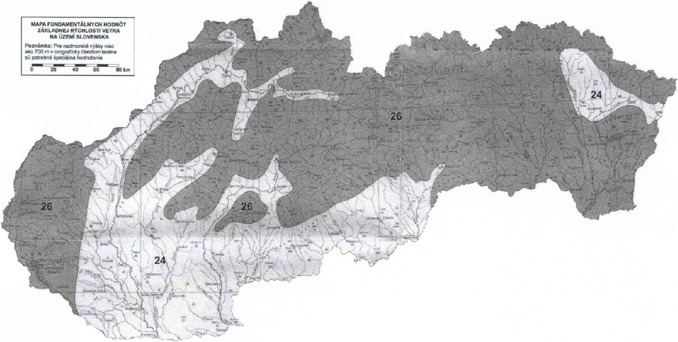
| Wind region | Wind velocity [m/s] |
|---|---|
| 1 | 24 |
| 2 | 26 |
| For altitude from 700 m to 1300 m | 30 |
| For altitude greater than 1300 m | 33 |
| Roof type | Zone | ||||||||
|---|---|---|---|---|---|---|---|---|---|
| F | G | H | I | ||||||
| cpe,10 | cpe,1 | cpe,10 | cpe,1 | cpe,10 | cpe,1 | cpe,10 | cpe,1 | ||
| Sharp eaves | -1,9 | -2,5 | -1,3 | -2,0 | -0,7 | -1,2 | +0,2 | ||
| -0,2 | |||||||||
| With parapets | hp / e = 0,025 | -1,7 | -2,2 | -1,2 | -1,8 | -0,7 | -1,2 | +0,2 | |
| -0,2 | |||||||||
| hp / e = 0,05 | -1,6 | -2,0 | -1,1 | -1,6 | -0,7 | -1,2 | +0,2 | ||
| -0,2 | |||||||||
| hp / e = 0,10 | -1,3 | -1,8 | -0,9 | -1,4 | -0,7 | -1,2 | +0,2 | ||
| -0,2 | |||||||||
| Curved eaves | r/h = 0,05 | -1,0 | -1,5 | -1,2 | -1,8 | -0,4 | +0,2 | ||
| -0,2 | |||||||||
| r/h = 0,10 | -0,7 | -1,2 | -0,8 | -1,4 | -0,3 | +0,2 | |||
| -0,2 | |||||||||
| r/h = 0,20 | -0,5 | -0,8 | -0,5 | -0,8 | -0,3 | +0,2 | |||
| -0,2 | |||||||||
| Mansard eaves | α = 30° | -1,0 | -1,5 | -1,0 | -1,5 | -0,3 | +0,2 | ||
| -0,2 | |||||||||
| α = 45° | -1,2 | -1,8 | -1,3 | -1,9 | -0,4 | +0,2 | |||
| -0,2 | |||||||||
| α = 60° | -1,3 | -1,9 | -1,3 | -1,9 | -0,6 | +0,2 | |||
| -0,2 | |||||||||
| Pitch angle α | Zone for wind direction θ = 0 ° | Zone for wind direction θ = 90 ° | Zone for wind direction θ = 180 ° | |||||||||||||||||||
|---|---|---|---|---|---|---|---|---|---|---|---|---|---|---|---|---|---|---|---|---|---|---|
| F | G | H | Fup | Flow | G | H | I | F | G | H | ||||||||||||
| cpe,10 | cpe,1 | cpe,10 | cpe,1 | cpe,10 | cpe,1 | cpe,10 | cpe,1 | cpe,10 | cpe,1 | cpe,10 | cpe,1 | cpe,10 | cpe,1 | cpe,10 | cpe,1 | cpe,10 | cpe,1 | cpe,10 | cpe,1 | cpe,10 | cpe,1 | |
| + 5° | -1,75 | -2,5 | -1,2 | -2,0 | -0,6 | -1,2 | -2,2 | -2,6 | -2,1 | -2,4 | -1,4 | -2,0 | -0,65 | -1,2 | -0,6 | -2,35 | -2,5 | -1,2 | -2,0 | -0,8 | -1,2 | |
| +0,0 | +0,0 | +0,0 | ||||||||||||||||||||
| + 15° | -1,0 | -2,0 | -0,8 | -1,5 | -0,35 | -2,5 | -2,9 | -1,6 | -2,4 | -1,5 | -2,5 | -0,8 | -1,2 | -0,75 | -1,2 | -2,5 | -2,8 | -1,2 | -2,0 | -0,9 | -1,2 | |
| +0,2 | +0,2 | +0,2 | ||||||||||||||||||||
| + 30° | -0,5 | -1,5 | -0,5 | -1,5 | -0,2 | -1,9 | -2,9 | -1,3 | -2,0 | -1,35 | -2,0 | -1,0 | -1,3 | -0,8 | -1,2 | -1,4 | -2,3 | -0,9 | -1,5 | -0,85 | ||
| +0,75 | +0,6 | +0,4 | +0,5 | +0,5 | +0,4 | +0,3 | +0,2 | |||||||||||||||
| + 45° | -0,0 | -0,0 | -0,0 | -1,5 | -2,4 | -1,3 | -2,0 | -1,3 | -2,0 | -1,0 | -1,3 | -0,9 | -1,2 | -0,75 | -1,3 | -0,65 | -0,8 | |||||
| +0,75 | +0,65 | +0,65 | +0,6 | +0,6 | +0,5 | +0,4 | +0,3 | |||||||||||||||
| + 60° | +0,75 | +0,75 | +0,75 | -1,2 | -2,0 | -1,2 | -2,0 | -1,2 | -2,0 | -0,7 | -1,3 | -0,4 | -1,2 | -0,75 | -1,0 | -0,6 | -0,6 | |||||
| +0,7 | +0,7 | +0,7 | +0,6 | +0,5 | ||||||||||||||||||
| + 75° | +0,8 | +0,8 | +0,8 | -1,2 | -2,0 | -1,2 | -2,0 | -1,2 | -2,0 | -0,7 | -1,3 | -0,35 | -0,75 | -1,0 | -0,6 | -0,6 | ||||||
| +0,8 | +0,8 | +0,8 | +0,7 | +0,6 | ||||||||||||||||||
| Pitch angle α | Zone for wind direction θ = 0 ° | Zone for wind direction θ = 90 ° | ||||||||||||||||
|---|---|---|---|---|---|---|---|---|---|---|---|---|---|---|---|---|---|---|
| F | G | H | I | J | F | G | H | I | ||||||||||
| cpe,10 | cpe,1 | cpe,10 | cpe,1 | cpe,10 | cpe,1 | cpe,10 | cpe,1 | cpe,10 | cpe,1 | cpe,10 | cpe,1 | cpe,10 | cpe,1 | cpe,10 | cpe,1 | cpe,10 | cpe,1 | |
| - 45° | -0,75 | -0,7 | -0,85 | -0,7 | -1,0 | -1,5 | -1,45 | -2,0 | -1,25 | -2,0 | -1,0 | -1,3 | -0,9 | -1,2 | ||||
| - 30° | -1,4 | -2,0 | -0,9 | -1,5 | -0,85 | -0,7 | -0,8 | -1,4 | -1,6 | -2,1 | -1,25 | -2,0 | -1,0 | -1,3 | -0,9 | -1,2 | ||
| - 15° | -2,55 | -2,8 | -1,2 | -2,0 | -0,9 | -1,2 | -0,5 | -0,7 | -1,2 | -2,2 | -2,5 | -1,3 | -2,0 | -0,8 | -1,2 | -0,8 | -1,2 | |
| - 5° | -2,35 | -2,5 | -1,2 | -2,0 | -0,8 | -1,2 | -0,5 | -0,5 | -2,0 | -2,5 | -1,35 | -2,0 | -0,7 | -1,2 | -0,65 | -1,2 | ||
| +0,2 | +0,2 | |||||||||||||||||
| + 5° | -1,75 | -2,5 | -1,2 | -2,0 | -0,6 | -1,2 | -0,5 | -0,7 | -1,8 | -2,2 | -1,2 | -2,0 | -0,65 | -1,2 | -0,55 | |||
| +0,0 | +0,0 | +0,0 | +0,2 | |||||||||||||||
| + 15° | -1,0 | -2,0 | -0,8 | -1,5 | -0,35 | -0,5 | -1,1 | -1,5 | -1,45 | -2,0 | -1,4 | -2,0 | -0,6 | -1,2 | -0,45 | |||
| +0,2 | +0,2 | +0,2 | +0,0 | +0,0 | ||||||||||||||
| + 30° | -0,5 | -1,5 | -0,5 | -1,5 | -0,2 | -0,45 | -0,7 | -1,15 | -1,5 | -1,25 | -2,0 | -0,7 | -1,2 | -0,5 | ||||
| +0,75 | +0,5 | +0,4 | +0,0 | +0,0 | ||||||||||||||
| + 45° | -0,0 | -0,0 | -0,0 | -0,25 | -0,3 | -1,15 | -1,5 | -1,3 | -2,0 | -0,75 | -1,2 | -0,45 | ||||||
| +0,75 | +0,65 | +0,65 | +0,0 | +0,0 | ||||||||||||||
| + 60° | +0,75 | +0,75 | +0,75 | -0,4 | -0,6 | -1,15 | -1,5 | -1,2 | -2,0 | -0,75 | -1,0 | -0,55 | ||||||
| + 75 ° | +0,8 | +0,8 | +0,8 | -0,5 | -0,6 | -1,15 | -1,5 | -1,2 | -2,0 | -1,0 | -0,55 | |||||||
| Pitch angle α | Zone for wind direction θ = 0 ° and θ = 90 ° | |||||||||||||||||
|---|---|---|---|---|---|---|---|---|---|---|---|---|---|---|---|---|---|---|
| F | G | H | I | J | K | L | M | N | ||||||||||
| cpe,10 | cpe,1 | cpe,10 | cpe,1 | cpe,10 | cpe,1 | cpe,10 | cpe,1 | cpe,10 | cpe,1 | cpe,10 | cpe,1 | cpe,10 | cpe,1 | cpe,10 | cpe,1 | cpe,10 | cpe,1 | |
| - 45° | -1,4 | -1,0 | -1,0 | -0,7 | -0,7 | -0,4 | -1,1 | -1,0 | -0,9 | |||||||||
| - 30° | -2,3 | -1,2 | -1,0 | -0,7 | -1,3 | -0,8 | -1,0 | -1,0 | -0,8 | |||||||||
| - 15° | -2,6 | -1,0 | -0,9 | -0,6 | -1,4 | -1,3 | -0,9 | -0,9 | -0,8 | |||||||||
| - 5° | -2,3 | -1,1 | -0,8 | -0,6 | -0,8 | -0,6 | -1,0 | -1,0 | -0,8 | |||||||||
| + 5 ° | -1,8 | -2,5 | -1,2 | -2,0 | -0,6 | -1,2 | -0,6 | -0,8 | -0,6 | -1,2 | -2,0 | -0,6 | -1,2 | -0,5 | ||||
| +0,0 | +0,0 | +0,0 | +0,0 | +0,0 | +0,0 | |||||||||||||
| + 15 ° | -1,1 | -2,0 | -0,8 | -1,5 | -0,4 | -0,6 | -1,2 | -1,5 | -1,3 | -2,0 | -1,0 | -2,0 | -0,6 | -1,2 | -0,35 | |||
| +0,2 | +0,2 | +0,2 | +0,0 | +0,0 | +0,0 | |||||||||||||
| + 30 ° | -0,5 | -1,5 | -0,5 | -1,5 | -0,2 | -0,6 | -1,3 | -0,65 | -1,1 | -2,0 | -0,7 | -1,2 | -0,4 | |||||
| +0,65 | +0,6 | +0,4 | +0,0 | +0,0 | +0,0 | |||||||||||||
| + 45 ° | -0,0 | -0,0 | -0,0 | -0,4 | -0,7 | -0,35 | -1,2 | -2,0 | -1,0 | -1,2 | -0,3 | |||||||
| +0,75 | +0,65 | +0,65 | +0,0 | +0,0 | +0,0 | |||||||||||||
| + 60 ° | +0,75 | +0,75 | +0,75 | -0,7 | -0,6 | -0,3 | -1,2 | -2,0 | -0,55 | -0,4 | ||||||||
| + 75 ° | +0,8 | +0,8 | +0,8 | -1,2 | -0,6 | -0,3 | -1,2 | -2,0 | -0,45 | -0,4 | ||||||||