This document contains all National annex values, which are used in SDF - Basic package
| Wind region | Wind velocity [m/s] |
|---|---|
| 1 | 29,5 |
| 2 | 27 |
| 3 | 24,5 |
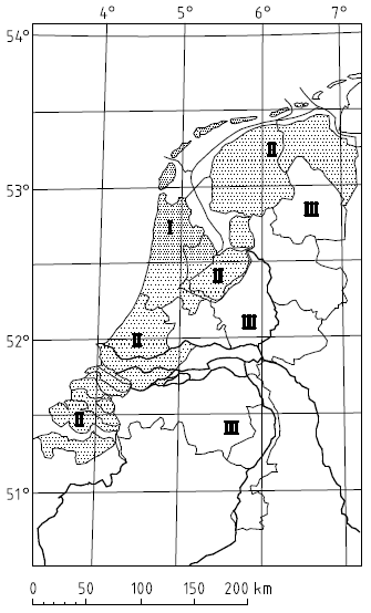
| Terrain category | z0 [m] |
zmin [m] |
|---|---|---|
| 0 Sea or coast by the sea | 0,005 | 0,1 |
| II Agricultural area | 0,2 | 4 |
| III Urban areas | 0,5 | 7 |
| Zone | A | B | C | D | E | |||||
|---|---|---|---|---|---|---|---|---|---|---|
| h/d | cpe,10 | cpe,1 | cpe,10 | cpe,1 | cpe,10 | cpe,1 | cpe,10 | cpe,1 | cpe,10 | cpe,1 |
| 5 | -1,2 | -1,4 | -0,8 | -1,1 | -0,5 | +0,8 | +1,0 | -0,7 | ||
| ≤ 1 | -1,2 | -1,4 | -0,8 | -1,1 | -0,5 | +0,8 | +1,0 | -0,5 | ||
| Roof type | Zone | ||||||||
|---|---|---|---|---|---|---|---|---|---|
| F | G | H | I | ||||||
| cpe,10 | cpe,1 | cpe,10 | cpe,1 | cpe,10 | cpe,1 | cpe,10 | cpe,1 | ||
| Sharp eaves | -1,8 | -2,5 | -1,2 | -2,0 | -0,7 | -1,2 | +0,2 | ||
| -0,2 | -0,5 | ||||||||
| With parapets | hp / e = 0,025 | -1,6 | -2,2 | -1,1 | -1,8 | -0,7 | -1,2 | +0,2 | |
| -0,2 | -0,5 | ||||||||
| hp / e = 0,05 | -1,4 | -2,0 | -0,9 | -1,6 | -0,7 | -1,2 | +0,2 | ||
| -0,2 | -0,5 | ||||||||
| hp / e = 0,10 | -1,2 | -1,8 | -0,8 | -1,4 | -0,7 | -1,2 | +0,2 | ||
| -0,2 | -0,5 | ||||||||
| Curved eaves | r/h = 0,05 | -1,0 | -1,5 | -1,2 | -1,8 | -0,4 | -1,0 | +0,2 | |
| -0,2 | -0,5 | ||||||||
| r/h = 0,10 | -0,7 | -1,2 | -0,8 | -1,4 | -0,3 | -1,0 | +0,2 | ||
| -0,2 | -0,5 | ||||||||
| r/h = 0,20 | -0,5 | -0,8 | -0,5 | -0,8 | -0,3 | -0,8 | +0,2 | ||
| -0,2 | -0,5 | ||||||||
| Mansard eaves | α = 30° | -1,0 | -1,5 | -1,0 | -1,5 | -0,3 | -1,0 | +0,2 | |
| -0,2 | -0,5 | ||||||||
| α = 45° | -1,2 | -1,8 | -1,3 | -1,9 | -0,4 | -1,2 | +0,2 | ||
| -0,2 | -0,5 | ||||||||
| α = 60° | -1,3 | -1,9 | -1,3 | -1,9 | -0,5 | -1,2 | +0,2 | ||
| -0,2 | -0,5 | ||||||||
| Pitch angle α | Zone for wind direction θ = 0 ° | Zone for wind direction θ = 90 ° | Zone for wind direction θ = 180 ° | |||||||||||||||||||
|---|---|---|---|---|---|---|---|---|---|---|---|---|---|---|---|---|---|---|---|---|---|---|
| F | G | H | Fup | Flow | G | H | I | F | G | H | ||||||||||||
| cpe,10 | cpe,1 | cpe,10 | cpe,1 | cpe,10 | cpe,1 | cpe,10 | cpe,1 | cpe,10 | cpe,1 | cpe,10 | cpe,1 | cpe,10 | cpe,1 | cpe,10 | cpe,1 | cpe,10 | cpe,1 | cpe,10 | cpe,1 | cpe,10 | cpe,1 | |
| + 5 ° | -1,7 | -2,5 | -1,2 | -2,0 | -0,6 | -1,2 | -2,1 | -2,6 | -2,1 | -2,4 | -1,8 | -2,0 | -0,6 | -1,2 | -0,5 | -1,0 | -2,3 | -2,5 | -1,3 | -2,0 | -0,8 | -1,2 |
| +0,0 | +0,0 | +0,0 | ||||||||||||||||||||
| + 15 ° | -0,9 | -2,0 | -0,8 | -1,5 | -0,3 | -1,0 | -2,4 | -2,9 | -1,6 | -2,4 | -1,9 | -2,5 | -0,8 | -1,2 | -0,7 | -1,2 | -2,5 | -2,8 | -1,3 | -2,0 | -0,9 | -1,2 |
| +0,2 | +0,2 | +0,2 | ||||||||||||||||||||
| + 30 ° | -0,5 | -1,5 | -0,5 | -1,5 | -0,2 | -1,0 | -2,1 | -2,9 | -1,3 | -2,0 | -1,5 | -2,0 | -1,0 | -1,3 | -0,8 | -1,2 | -1,1 | -2,3 | -0,8 | -1,5 | -0,8 | -1,0 |
| +0,4 | +0,4 | +0,4 | ||||||||||||||||||||
| + 45 ° | -0,0 | -0,0 | -0,0 | -1,5 | -2,4 | -1,3 | -2,0 | -1,4 | -2,0 | -1,0 | -1,3 | -0,9 | -1,2 | -0,6 | -1,3 | -0,5 | -1,0 | -0,7 | -1,0 | |||
| +0,7 | +0,7 | +0,6 | ||||||||||||||||||||
| + 60 ° | +0,7 | +0,7 | +0,7 | -1,2 | -2,0 | -1,2 | -2,0 | -1,2 | -2,0 | -1,0 | -1,3 | -0,7 | -1,2 | -0,5 | -1,0 | -0,5 | -1,0 | -0,5 | -1,0 | |||
| + 75 ° | +0,8 | +0,8 | +0,8 | -1,2 | -2,0 | -1,2 | -2,0 | -1,2 | -2,0 | -1,0 | -1,3 | -0,5 | -1,0 | -0,5 | -1,0 | -0,5 | -1,0 | -0,5 | -1,0 | |||
| Pitch angle α | Zone for wind direction θ = 0 ° | Zone for wind direction θ = 90 ° | ||||||||||||||||
|---|---|---|---|---|---|---|---|---|---|---|---|---|---|---|---|---|---|---|
| F | G | H | I | J | F | G | H | I | ||||||||||
| cpe,10 | cpe,1 | cpe,10 | cpe,1 | cpe,10 | cpe,1 | cpe,10 | cpe,1 | cpe,10 | cpe,1 | cpe,10 | cpe,1 | cpe,10 | cpe,1 | cpe,10 | cpe,1 | cpe,10 | cpe,1 | |
| - 45 ° | -0,6 | -0,6 | -0,8 | -0,7 | -1,0 | -1,5 | -1,4 | -2,0 | -1,2 | -2,0 | -1,0 | -1,3 | -0,9 | -1,2 | ||||
| - 30 ° | -1,1 | -2,0 | -0,8 | -1,5 | -0,8 | -0,6 | -0,8 | -1,4 | -1,5 | -2,1 | -1,2 | -2,0 | -1,0 | -1,3 | -0,9 | -1,2 | ||
| - 15 ° | -2,5 | -2,8 | -1,3 | -2,0 | -0,9 | -1,2 | -0,5 | -0,7 | -1,2 | -1,9 | -2,5 | -1,2 | -2,0 | -0,8 | -1,2 | -0,8 | -1,2 | |
| - 5 ° | -2,3 | -2,5 | -1,2 | -2,0 | -0,8 | -1,2 | -0,6 | -0,6 | -1,0 | -1,8 | -2,5 | -1,2 | -2,0 | -0,7 | -1,2 | -0,6 | -1,2 | |
| +0,2 | +0,2 | |||||||||||||||||
| + 5 ° | -1,7 | -2,5 | -1,2 | -2,0 | -0,6 | -1,2 | -0,6 | -1,0 | -0,6 | -1,0 | -1,6 | -2,2 | -1,3 | -2,0 | -0,7 | -1,2 | -0,6 | -1,0 |
| +0,0 | +0,0 | +0,0 | +0,2 | |||||||||||||||
| + 15 ° | -0,9 | -2,0 | -0,8 | -1,5 | -0,3 | -1,0 | -0,4 | -1,0 | -1,0 | -1,5 | -1,3 | -2,0 | -1,3 | -2,0 | -0,6 | -1,2 | -0,5 | -1,0 |
| +0,2 | +0,2 | +0,2 | +0,0 | +0,0 | ||||||||||||||
| + 30 ° | -0,5 | -1,5 | -0,5 | -1,5 | -0,2 | -1,0 | -0,4 | -1,0 | -0,5 | -1,0 | -1,1 | -1,5 | -1,4 | -2,0 | -0,8 | -1,2 | -0,5 | -1,0 |
| +0,7 | +0,7 | +0,4 | +0,0 | +0,0 | ||||||||||||||
| + 45 ° | -0,0 | -0,0 | -0,0 | -0,2 | -1,0 | -0,3 | -1,0 | -1,1 | -1,5 | -1,4 | -2,0 | -0,9 | -1,2 | -0,5 | -1,0 | |||
| +0,7 | +0,7 | +0,6 | +0,0 | +0,0 | ||||||||||||||
| + 60 ° | +0,7 | +0,7 | +0,7 | -0,2 | -1,0 | -0,3 | -1,0 | -1,1 | -1,5 | -1,2 | -2,0 | -0,8 | -1,0 | -0,5 | -1,0 | |||
| + 75 ° | +0,8 | +0,8 | +0,8 | -0,2 | -1,0 | -0,3 | -1,0 | -1,1 | -1,5 | -1,2 | -2,0 | -0,8 | -1,0 | -0,5 | -1,0 | |||
| Pitch angle α | Zone for wind direction θ = 0 ° and θ = 90 ° | |||||||||||||||||
|---|---|---|---|---|---|---|---|---|---|---|---|---|---|---|---|---|---|---|
| F | G | H | I | J | K | L | M | N | ||||||||||
| cpe,10 | cpe,1 | cpe,10 | cpe,1 | cpe,10 | cpe,1 | cpe,10 | cpe,1 | cpe,10 | cpe,1 | cpe,10 | cpe,1 | cpe,10 | cpe,1 | cpe,10 | cpe,1 | cpe,10 | cpe,1 | |
| + 5 ° | -1,7 | -2,5 | -1,2 | -2,0 | -0,6 | -1,2 | -0,3 | -1,0 | -0,6 | -1,0 | -0,6 | -1,0 | -1,2 | -2,0 | -0,6 | -1,2 | -0,4 | -1,0 |
| +0,0 | +0,0 | +0,0 | ||||||||||||||||
| + 15 ° | -0,9 | -2,0 | -0,8 | -1,5 | -0,3 | -1,0 | -0,5 | -1,0 | -1,0 | -1,5 | -1,2 | -2,0 | -1,4 | -2,0 | -0,6 | -1,2 | -0,3 | -1,0 |
| +0,2 | +0,2 | +0,2 | ||||||||||||||||
| + 30 ° | -0,5 | -1,5 | -0,5 | -1,5 | -0,2 | -1,0 | -0,4 | -1,0 | -0,7 | -1,2 | -0,5 | -1,0 | -1,4 | -2,0 | -0,8 | -1,2 | -0,2 | -1,0 |
| +0,5 | +0,7 | +0,4 | ||||||||||||||||
| + 45 ° | -0,0 | -0,0 | -0,0 | -0,4 | -1,0 | -0,6 | -1,0 | -0,3 | -1,0 | -1,3 | -2,0 | -0,8 | -1,2 | -0,2 | -1,0 | |||
| +0,7 | +0,7 | +0,6 | ||||||||||||||||
| + 60 ° | +0,7 | +0,7 | +0,7 | -0,3 | -1,0 | -0,6 | -1,0 | -0,3 | -1,0 | -1,2 | -2,0 | -0,4 | -1,0 | -0,2 | -1,0 | |||
| + 75 ° | +0,8 | +0,8 | +0,8 | -0,3 | -1,0 | -0,6 | -1,0 | -0,3 | -1,0 | -1,2 | -2,0 | -0,4 | -1,0 | -0,2 | -1,0 | |||
| Solidity | Zone | A | B | C | D | |
|---|---|---|---|---|---|---|
| φ = 1 | Without return corner | l/h ≤ 3 | 2,3 | 1,4 | 1,2 | 1,2 |
| l/h = 5 | 2,9 | 1,8 | 1,4 | 1,2 | ||
| l/h ≥ 10 | 3,4 | 2,1 | 1,7 | 1,2 | ||
| With return corners of length ≥ h | 2,1 | 1,8 | 1,4 | 1,2 | ||
| φ = 0,8 | 1,2 | 1,2 | 1,2 | 1,2 | ||