Documentation
This document contains all National annex values, which are used in SDF - Basic package
Clause 4.2 The fundamental value of the basic wind velocity vb,0, paragraph (1)P, NOTE 2
The fundamental value of the basic wind velocity vb,0 should be determined as follows:
vb,0 = vb,map • calt
where:
vb,map is the value of the fundamental basic wind velocity before the altitude correction is applied. Values are given in Figure NA.1
calt is the altitude factor given in Clause 4.2, paragrahp 1(P), NOTE 1
Figure NA.1 - Map of fundamental basic wind velocity values vb,map [m/s] before the altitude correction is applied

NOTE 1 This map is intended for sites in the United Kingdon, Isle of Man and Channel Islands only.
NOTE 2 The isopleths in the Irish Republic are shown for purposes of interpolation only.
Clause 4.2 Procedure for determining the influence of altitude, paragraph (2)P, NOTE 1
The altitude factor calt should be determined as follows:
calt = 1 + 0,001•A for z ≤ 10 m
calt = 1 + 0,001•A•(10/z)0,2 for z > 10 m
A is the altitude of the site in metres above mean sea level
z is the height of the part above ground in which the wind pressure is calculated in metres
Clause 4.2 Directional factor cdir, paragraph (2)P, NOTE 2
The directional factor cdir is given in Table NA.1
Table NA.1 - Directional factor cdir
| Azimuth |
0° |
30° |
60° |
90° |
120° |
150° |
180° |
210° |
240° |
270° |
300° |
330° |
| cdir |
0,78 |
0,73 |
0,73 |
0,74 |
0,73 |
0,80 |
0,85 |
0,93 |
1,00 |
0,99 |
0,91 |
0,82 |
NOTE 1 Interpolation may be used within Table NA.l.
NOTE 2 The directions are defined by angles from due North in a clockwise direction.
Clause 4.2 Season factor cseason, paragraph (2)P, NOTE 3
Table NA.2 - Season factor cseason
| Months |
1 month |
2 months |
4 months |
Half a year |
| January |
0,98 |
0,98 |
|
0,98 |
|
|
| February |
0,83 |
0,86 |
0,87 |
|
|
| March |
0,82 |
0,83 |
0,83 |
|
|
| April |
0,75 |
0,75 |
0,76 |
0,84 |
| May |
0,69 |
0,71 |
0,73 |
| June |
0,66 |
0,67 |
0,83 |
| July |
0,62 |
0,71 |
0,86 |
| August |
0,71 |
0,82 |
0,90 |
| September |
0,82 |
0,85 |
0,96 |
| October |
0,82 |
0,89 |
1,00 |
1,00 |
| November |
0,88 |
0,95 |
1,00 |
| December |
0,94 |
1,00 |
1,00 |
| January |
|
|
|
| February |
|
|
|
| March |
|
|
|
Clause 4.3.1 Orography factor cO, paragraph (1), NOTE 1
The recommended procedure given in Annex A.3 should be used.
Clause 4.3.1 Design charts for vm, paragraph (1), NOTE 2
Design charts for vm are not provided.
Clause 4.3.2 Procedure for determining the roughness factor cr, paragraph (1)
Expressions from standard are not used in BS.
The classification of roughness categories has been simplified to give the following three terrain categories:
- Terrain category 0 is referred to as "Sea".
- Terrain categories I and II have been considered together to give a single terrain category referred to as "Country terrain".
- Terrain categories III and IV have been considered together to give a single terrain category referred to as "Town terrain".
All inland lakes extending more than 1 km in the direction of wind and closer than 1 km upwind of the site should be treated as Sea.
The roughness factor cr depends on upwind distance to sea and additionally on the distance upwind to the edge of the urban area for sites in Town terrain.
For sites in Country terrain, the roughness factor cr given in Figure NA.3 should be used.
For sites adjacent to Sea terrain (sea or large inland lakes), the distance upwind from the shoreline should be taken as 0,1 km and Figure NA.3 should be used.
For sites in Town terrain, the roughness factor cr given in Figure NA.3 should be multiplied by the roughness correction factor cr,T for Town terrain given in Figure NA.4.
The appropriate value of hdis is to be used in Figure NA.3 and Figure NA.4. For sites in Sea and Country terrain, hdis = 0. For sites in Tow terrain, hdis is given by Annex A.5 in standard.
Figure NA.3 - Values of cr

Figure NA.4 - Values of correction factor cr,T for sites in Town terrain
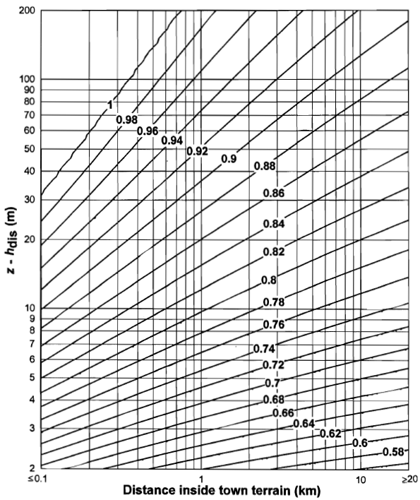
NOTE: Sites less than 0.1 km inside Town boundary should be treated as being in country terrain.
Clause 4.3.3 Procedure for determining the orography factor, paragraph (1)
The recommended procedure from A.3 should be used for sites that lie in the shaded zones shown in Figure NA.2. Outside of these zones, the orography factor may be taken as 1,0.
Figure NA.2 - Definition of significant orography for A.3

Clause 4.3.5 Effect of closely spaced buildings and obstacles, paragraph (1)
The recommended procedure from A.5 may be used.
Clause 4.4 Determination of the turbulence factor kI, paragraph (1), Note 2
Values for turbulence factor kI on its own are not given.
Turbulence intensity Iv is directly given in Figure NA.5 as Iv(z)flat. It depends on upwind distance to sea and additionally on the distance upwind to the edge of the urban area for sites in Town terrain.
For sites in Country terrain, the turbulence intensity Iv(z)flat given in Figure NA.5 should be used.
For sites adjacent to Sea terrain (sea or large inland lakes), the distance upwind from the shoreline should be taken as 0,1 km and Figure NA.5 should be used.
For sites in Town terrain, the turbulence intensity Iv(z)flat given in Figure NA.5 should be multiplied by the turbulence correction factor kI,T for Town terrain given in Figure NA.6.
Sites less than 0.1 km inside Town boundary should be treated as being in country terrain.
If orography is significant, the Turbulence intensity should be divided by the orography factor cO
Figure NA.5 - Values of Iv(z)flat

Figure NA.6 - Values of kI,T

Clause 4.5 Determination of peak velocity pressure qp, paragraph (1), Note 1
Expression from Standard does not apply.
qb = 0,5 • ρ • vb2
When orography is not significant (cO = 1,0) :
qp = ce,diag • qb for sites in Country terrain.
For sites adjacent to Sea terrain (sea or large inland lakes), the distance upwind from the shoreline should be taken as 0,1 km and Figure NA.7 should be used.
qp = ce,diag • ce,T • qb for sites in Town terrain.
The value ce,diag is given in Figure NA.7
The value ce,T is given in Figure NA.8
When orography is significant :
qp = (qp from insignificant orography) • [(cO + 0,6) / 1,6]2 for z ≤ 50 m.
qp = [1 + 3,0 • Iv]2 • 0,5 • ρ • vm2 for z ≥ 50 m.
Figure NA.7 - Values of ce,diag

Figure NA.8 - Values of ce,T

Clause 4.5 Value to be used for air density ρ, paragraph (1), Note 2
ρ = 1,226 kg/m3 in BS
Clause 6.1 Separation of the structural factor cscd into a separate size factor cs and dynamic factor cd, paragraph (1)
The structural factor cscd may be separated in to a size factor cs and a dynamic factor cd
Expressions from Standard code are used.
Clause 6.3.1 Procedure to determine peak, background and resonance response factors, paragraph (1), Note 3
The recommended procedure given in Standard code, Annex B should be used.
Clause 7.2.1 Procedure for determining the external pressure coefficient for loaded areas between 1 m2 and 10 m2, paragraph (1), Note 2
Figure from Standard should not be used.
Cpe,1 values should be used for loaded areas 1 m2 and Cpe,10 values should be used for loaded areas > 1 m2.
Clause 7.2.2 Values of external pressure coefficients for vertical walls of rectangular-plan buildings, paragraph (2), Note 1
The Table 7.1 from Standard should not be used. New Table NA.4 should be used.
Table NA.4 - Values of external pressure coefficients for vertical walls of rectangular-plan buildings (Cpe,l0 and Cpe,1)
| h/d |
Zone |
| A |
B |
C |
D |
E |
| 5 |
-1,2 |
-0,8 |
-0,5 |
+0,8 |
-0,7 |
| 1 |
-1,2 |
-0,8 |
-0,5 |
+0,8 |
-0,5 |
| ≤ 0,25 |
-1,2 |
-0,8 |
-0,5 |
+0,7 |
-0,3 |
Clause 7.2.3 Pressure coefficients for flat roofs, paragraph (4), Note 1
The Table 7.2 from Standard should not be used. New Table NA.5 should be used.
Table NA.5 - External pressure coefficients for flat roofs (Cpe,l0 and Cpe,1)
| Roof type |
Zone |
| F |
G |
H |
I |
| Sharp eaves |
-2,0 |
-1,4 |
-0,7 |
-0,2 |
| 0,2 |
| With parapets |
hp/e = 0,05 |
-1,9 |
-1,3 |
-0,7 |
-0,2 |
| 0,2 |
| hp/e = 0,10 |
-1,85 |
-1,3 |
-0,7 |
-0,2 |
| 0,2 |
| hp/e ≥ 0,20 |
-1,4 |
-1,0 |
-0,7 |
-0,2 |
| 0,2 |
| Curved eaves |
r/e = 0,05 |
-1,05 |
-1,2 |
-0,4 |
-0,2 |
| 0,2 |
| r/e = 0,10 |
-0,75 |
-0,8 |
-0,3 |
-0,2 |
| 0,2 |
| r/e = 0,20 |
-0,55 |
-0,55 |
-0,3 |
-0,2 |
| 0,2 |
| Mansard eaves |
α = 30° |
-0,95 |
-1,0 |
-0,3 |
-0,2 |
| 0,2 |
| α = 45° |
-1,2 |
-1,3 |
-0,4 |
-0,2 |
| 0,2 |
| α = 60° |
-1,35 |
-1,25 |
-0,6 |
-0,2 |
| 0,2 |
For roofs with parapets or curved eaves, linear interpolation is used for intermediate values of hp/h and r/h.
For roofs with mansard eaves, linear interpolation between α = 30°, 45° and α = 60° is used. For α > 60° linear interpolation between the values for α = 60° and the values for flat roofs with sharp eaves is used.
Clause 7.2.4 Pressure coefficients for monopitch roofs, paragraph (3), Note 1
The Tables 7.3a and 7.3b from Standard should not be used. New Tables NA.6a and NA.6b should be used.
Table NA.6a - External pressure coefficients for monopitch roofs (Cpe,l0 and Cpe,1)
| Pitch angle α |
Zone for wind direction θ = 0 ° |
Zone for wind direction θ = 180 ° |
| F |
G |
H |
F |
G |
H |
| 5° |
-1,8 |
-1,2 |
-0,6 |
-2,4 |
-1,1 |
-0,8 |
| +0,0 |
+0,0 |
+0,0 |
| 15° |
-1,1 |
-0,8 |
-0,4 |
-2,6 |
-1,0 |
-0,9 |
| +0,2 |
+0,2 |
+0,2 |
| 30° |
-0,5 |
-0,5 |
-0,2 |
-1,7 |
-1,0 |
-0,9 |
| +0,8 |
+0,5 |
+0,4 |
| 45° |
-0,0 |
-0,0 |
-0,0 |
-0,9 |
-0,8 |
-0,9 |
| +0,8 |
+0,6 |
+0,7 |
| 60° |
+0,8 |
+0,8 |
+0,8 |
-1,0 |
-0,7 |
-0,7 |
| 75° |
+0,8 |
+0,8 |
+0,8 |
-1,1 |
-0,7 |
-0,7 |
For roofs with pitch angle between 5 ° and 45 ° both positive and negative values are given. For these roofs, two cases should be considered, one with all positive values, and one with all negative values.
Linear interpolation is used between values of the same sign.
Table NA.6b - External pressure coefficients for monopitch roofs (Cpe,l0 and Cpe,1)
| Pitch angle α |
Zone for wind direction θ = 90 ° |
| Fup |
Flow |
G |
H |
I |
| 5° |
-2,2 |
-2,1 |
-1,1 |
-0,7 |
-0,7 |
| +0,0 |
+0,0 |
+0,0 |
+0,0 |
+0,0 |
| 15° |
-2,6 |
-1,6 |
-1,1 |
-0,8 |
-0,8 |
| +0,2 |
+0,2 |
+0,2 |
+0,2 |
+0,2 |
| 30° |
-1,7 |
-1,3 |
-1,2 |
-1,0 |
-0,8 |
| +0,5 |
+0,5 |
+0,4 |
+0,3 |
+0,2 |
| 45° |
-1,5 |
-1,3 |
-1,2 |
-1,0 |
-0,9 |
| +0,6 |
+0,6 |
+0,5 |
+0,4 |
+0,3 |
| 60° |
-1,2 |
-1,2 |
-1,2 |
-0,4 |
-0,2 |
| +0,7 |
+0,7 |
+0,7 |
+0,5 |
+0,5 |
| 75° |
-1,2 |
-1,2 |
-1,2 |
-0,4 |
-0,2 |
| +0,8 |
+0,8 |
+0,8 |
+0,7 |
+0,6 |
Linear interpolation is used between values of the same sign.
Clause 7.2.5 Pressure coefficients for duopitch roofs, paragraph (3), Note 1
The Tables 7.4a and 7.4b from Standard should not be used. New Tables NA.7a and NA.7b should be used.
Table NA.7a - External pressure coefficients for duopitch roofs (Cpe,l0 and Cpe,1)
| Pitch angle α |
Zone for wind direction θ = 0 ° |
| F |
G |
H |
I |
J |
| -45° |
-0,9 |
-0,8 |
-0,9 |
-0,7 |
-1,1 |
| -30° |
-1,7 |
-1,0 |
-0,9 |
-0,7 |
-0,8 |
| -15° |
-2,6 |
-1,0 |
-0,9 |
-0,5 |
-0,7 |
| -5° |
-2,4 |
-1,2 |
-0,8 |
-0,5 |
-0,5 |
| 5° |
-1,8 |
-1,2 |
-0,6 |
-0,4 |
-0,9 |
| +0,0 |
+0,0 |
+0,0 |
-0,4 |
-0,9 |
| 15° |
-1,1 |
-0,8 |
-0,4 |
-0,5 |
-1,3 |
| +0,2 |
+0,2 |
+0,2 |
-0,5 |
-1,3 |
| 30° |
-0,5 |
-0,5 |
-0,2 |
-0,5 |
-0,9 |
| +0,8 |
+0,5 |
+0,4 |
-0,5 |
-0,9 |
| 45° |
-0,0 |
-0,0 |
-0,0 |
-0,5 |
-0,8 |
| +0,8 |
+0,6 |
+0,7 |
-0,5 |
-0,8 |
| 60° |
+0,8 |
+0,8 |
+0,8 |
-0,6 |
-0,8 |
| 75° |
+0,8 |
+0,8 |
+0,8 |
-0,8 |
-0,9 |
For roofs with a pitch angle of α = -5° to +45°, so both positive and negative values are given. For those roofs, four cases are considered where the largest or smallest values of all areas F, G and H are combined with the largest or smallest values in areas I and J. No mixing of positive and negative values is allowed on the same face.
Linear interpolation is used between values of the same sign.
Table NA.7b - External pressure coefficients for duopitch roofs (Cpe,l0 and Cpe,1)
| Pitch angle α |
Zone for wind direction θ = 90 ° |
| F |
G |
H |
I |
| -45° |
-1,5 |
-1,3 |
-1,0 |
-0,9 |
| -30° |
-1,7 |
-1,3 |
-1,0 |
-0,8 |
| -15° |
-2,6 |
-1,4 |
-0,8 |
-0,8 |
| -5° |
-2,2 |
-1,5 |
-0,7 |
-0,7 |
| 5° |
-2,0 |
-1,1 |
-0,6 |
-0,5 |
| +0,0 |
+0,0 |
+0,0 |
+0,0 |
| 15° |
-1,6 |
-1,5 |
-0,6 |
-0,4 |
| +0,2 |
+0,2 |
+0,2 |
+0,2 |
| 30° |
-1,2 |
-1,1 |
-0,6 |
-0,5 |
| +0,5 |
+0,4 |
+0,3 |
+0,2 |
| 45° |
-1,2 |
-1,2 |
-0,6 |
-0,4 |
| +0,6 |
+0,5 |
+0,4 |
+0,3 |
| 60° |
-1,2 |
-1,2 |
-0,7 |
-0,6 |
| +0,7 |
+0,7 |
+0,5 |
+0,5 |
| 75° |
-1,2 |
-1,2 |
-0,7 |
-0,6 |
| +0,8 |
+0,8 |
+0,7 |
+0,6 |
Linear interpolation is used between values of the same sign.
Clause 7.2.6 Pressure coefficients for hipped roofs, paragraph (3), Note 1
The Table 7.5 from Standard should not be used. New Tables NA.7a and NA.7b should be used.
Table NA.7a - External pressure coefficients for duopitch roofs (Cpe,l0 and Cpe,1)
| Pitch angle α |
Zone for wind direction θ = 0 ° and θ = 90 ° |
| F |
G |
H |
I |
J |
K |
L |
M |
N |
| -45° |
-1,4 |
-1,0 |
-1,0 |
-0,7 |
-0,7 |
-0,4 |
-1,1 |
-1,0 |
-0,9 |
| -30° |
-2,3 |
-1,2 |
-1,0 |
-0,7 |
-1,3 |
-0,8 |
-1,0 |
-1,0 |
-0,8 |
| -15° |
-2,6 |
-1,0 |
-0,9 |
-0,6 |
-1,4 |
-1,3 |
-0,9 |
-0,9 |
-0,8 |
| -5° |
-2,3 |
-1,1 |
-0,8 |
-0,6 |
-0,8 |
-0,6 |
-1,1 |
-0,8 |
-0,8 |
| 5° |
-1,8 |
-1,2 |
-0,6 |
-0,6 |
-0,8 |
-0,6 |
-1,1 |
-0,6 |
-0,6 |
| +0,0 |
+0,0 |
+0,0 |
-0,6 |
-0,8 |
-0,6 |
+0,0 |
+0,0 |
+0,0 |
| 15° |
-1,3 |
-0,8 |
-0,5 |
-0,6 |
-1,4 |
-1,3 |
-0,9 |
-0,6 |
-0,4 |
| +0,2 |
+0,2 |
+0,2 |
-0,6 |
-1,4 |
-1,3 |
+0,0 |
+0,0 |
+0,0 |
| 30° |
-0,5 |
-0,5 |
-0,2 |
-0,6 |
-1,3 |
-0,8 |
-1,0 |
-0,6 |
-0,5 |
| +0,8 |
+0,5 |
+0,4 |
-0,6 |
-1,3 |
-0,8 |
+0,0 |
+0,0 |
+0,0 |
| 45° |
-0,0 |
-0,0 |
-0,0 |
-0,6 |
-0,7 |
-0,4 |
-1,1 |
-0,6 |
-0,4 |
| +0,8 |
+0,6 |
+0,7 |
-0,6 |
-0,7 |
-0,4 |
+0,0 |
+0,0 |
+0,0 |
| 60° |
+0,8 |
+0,8 |
+0,8 |
-0,7 |
-0,6 |
-0,3 |
-1,2 |
-0,7 |
-0,6 |
| 75° |
+0,8 |
+0,8 |
+0,8 |
-1,2 |
-0,6 |
-0,3 |
-1,2 |
-0,7 |
-0,6 |
The pressures changes rapidly between positive and negative values on the windward face at pitch angle of a +5° to +45°, so both positive and negative values are given. For those roofs, two cases should be considered: one with all positive values, and one with all negative values. Positive and negative values should not be mixed.
Linear interpolation for intermediate pitch angles of the same sign is used between values of the same sign.
Clause 7.2.8 Pressure coefficients for vaulted roofs and domes, paragraph (1), Note
Clause 7.3 Canopy roofs, paragraph (6)
The recommended values for the location of centre of pressure should be used.
Clause 7.4.1 Pressure coefficients for free-standing walls and parapets, paragraph (1)
The recommended values given in Standard should be used.
Clause 7.4.3 The value of the horizontal eccentricity, paragraph (2)
The recommended value given in Standard should be used.