Nepřihlášen

Seznam výpočtů Design Forms:

▶ EuroCode - EN 1993-1-1
Posouzení N+My+Mz
EuroCode - EN 1993-1-1 -
Autor: Design Forms s.r.o.
Vytvořen: 09.06.2016
Naposledy upraven: 13.10.2016
Popis:
Posouzení ocelového prutu na kombinaci N + My + Mz
Anotace:


Tabulka B.3 - Součinitele Cm ekvivalentního konstantního momentu


Posouzení ohybu za klopení
EuroCode - EN 1993-1-1 -
Autor: Design Forms s.r.o.
Vytvořen: 27.06.2016
Naposledy upraven: 29.08.2016
Popis:
Posouzení stability ocelového prutu za ohybu (klopení)
Anotace:

Obrázek NB 3.1. - Význam veličin a znaménková konvence při působení zatížení Fz


Obrázek NB 3.2. - Průřezy symetrické k ose největší tuhosti nebo centrálně symetrické


Tabulka NB 3.1. - Hodnoty součinitelů C1 a C3 při zatížení prutu koncovými momenty v závislosti na hodnotě  součinitele kz a součinitelů yf a kwt


Tabulka NB 3.2. - Hodnoty součinitelů C1, C2 a C3 pro různé případy příčného zatížení v závislosti na hodnotě součinitelů ky, kz, kw a součinitelů yf a kwt


Posouzení vzpěru
EuroCode - EN 1993-1-1 -
Autor: Design Forms s.r.o.
Vytvořen: 27.06.2016
Naposledy upraven: 29.08.2016
Popis:
Posouzení ocelového prutu na vzpěr
Anotace:


Tabulka 6.1. - Součinitele imperfekce pro křivky vzpěrné pevnosti


Křivka vzpěrné pevnosti a0 a b c d
Součinitele imperfekce a 0,13 0,21 0,34 0,49 0,76


Obrázek 6.4 - Křivky vzpěrné pevnosti


Tabulka 6.2 - Přiřazení křivek vzpěrné pevnosti k průřezům


Posouzení kruhového čepu
EuroCode - EN 1993-1-1 -
Autor: Design Forms s.r.o.
Vytvořen: 07.07.2016
Naposledy upraven: 29.08.2016
Popis:
Posouzení kruhového čepu
Anotace:


Tabulka 3.9 - Geometrické požadavky na pruty ukončené čepovými spoji


Obrázek 3.11 - Geometrie čepu


Posouzení vysokopevnostních šroubů
EuroCode - EN 1993-1-1 -
Autor: Design Forms s.r.o.
Vytvořen: 07.07.2016
Naposledy upraven: 29.08.2016
Popis:
Posouzení vysokopevnostních šroubů
Anotace:

Tabulka 3.6 - Hodnoty ks


Popis ks
Šrouby v obyčejných otvorech 1,00
Šrouby v nadměrných otvorech nebo krátkých prodloužených otvorech s osou prodlouženého otvork kolmou na směr síly 0,85
Šrouby v dlouhých prodloužených otvorech s osou prodlouženého otvoru kolmou na směr síly 0,70
Šrouby v krátkých prodloužených otvorech s osou prodlouženého otvoru ve směru síly 0,76
Šrouby v dlouhých prodloužených otvorech s osou prodlouženého otvoru ve směru síly 0,63


Tabulka 3.7 - Součinitel tření m pro předpjaté šrouby


Třída třecího povrchu (viz související normy 1.2.7; skupina 7) m
Tryskaný povrch s dokonale odstraněnou rzí; nebo tryskaný povrch s hliníkovým nebo zinkovým povlakem 0,50
Tryskaný povrch s alkalicko-zinkovým silikátovým nátěrem s tloušťkou 50-80 mm 0,40
Povrch čištěný kartáčem nebo plamenem 0,30
Bez úprav 0,20

Posouzení smyku
EuroCode - EN 1993-1-1 -
Autor: Design Forms s.r.o.
Vytvořen: 07.07.2016
Naposledy upraven: 29.08.2016
Popis:
Posouzení smyku ocelového průřezu
Anotace:
Check of shear

Posouzení smyku za ohybu
EuroCode - EN 1993-1-1 -
Autor: Design Forms s.r.o.
Vytvořen: 07.07.2016
Naposledy upraven: 29.08.2016
Popis:
Posouzení kombinace smyku a ohybového momentu
Anotace:
Check of shear and bending

Posouzení prostého ohybu
EuroCode - EN 1993-1-1 -
Autor: Design Forms s.r.o.
Vytvořen: 07.07.2016
Naposledy upraven: 29.08.2016
Popis:
Posouzení ocelového průřezu na prostý obyb
Anotace:
Check of simple bending

Posouzení prostého tlaku
EuroCode - EN 1993-1-1 -
Autor: Design Forms s.r.o.
Vytvořen: 07.07.2016
Naposledy upraven: 29.08.2016
Popis:
Check steel section in simple compression
Anotace:
Check of simple compression

Posouzení prostého tahu
EuroCode - EN 1993-1-1 -
Autor: Design Forms s.r.o.
Vytvořen: 07.07.2016
Naposledy upraven: 29.08.2016
Popis:
Posouzení ocelového prutu na tah
Anotace:
Check of simple tension

Posouzení svarů
EuroCode - EN 1993-1-1 -
Autor: Design Forms s.r.o.
Vytvořen: 10.10.2016
Naposledy upraven: 15.11.2016
Popis:
Posouzení svarů
Anotace:
Posouzení svarů

▶ EuroCode - EN 1992-1-1
Calculation of the anchor length
EuroCode - EN 1992-1-1 -
Autor: Design Forms s.r.o.
Vytvořen: 20.07.2016
Naposledy upraven: 27.09.2016
Popis:
Výpočet kotevní délky betonářské výztuže
Anotace:

Obrázek 8.1 - Způsoby kotvení jiné než přímou koncovou úpravou


8.4.2 Mezní napětí v soudržnosti


Obrázek 8.2 - Popis podmínek soudržnosti


Tabulka 8.2 - Hodnoty součinitelů a1, a2, a3, a4, a5


Krytí výztuže
EuroCode - EN 1992-1-1 -
Autor: Design Forms s.r.o.
Vytvořen: 20.07.2016
Naposledy upraven: 29.08.2016
Popis:
Výpočet nutného krytí betonářské výztuže
Anotace:


Hodnotu Dcdev, která se použije v příslušném státě, lze uvést v národní příloze. Doporučená hodnota je 10 mm.


Hodnotu Dcdur,st, která se použije v příslušném státě, lze uvést v národní příloze. Doporučená hodnota, bez další specifikace, je 0 mm.


Hodnotu Dcdur,g, která se použije v příslušném státě, lze uvést v národní příloze. Doporučená hodnota je 0 mm.


Hodnotu Dcdur,add, která se použije v příslušném státě, lze uvést v národní příloze. Doporučená hodnota, bez další specifikace, je 0 mm.


Tabulka 4.1 – Stupně vlivu prostředí podle EN 206-1


Tabulka 4.3 – Doporučená úprava klasifikace konstrukcí


Tabulka 4.4 – Minimální hodnoty krycí vrstvy cmin,dur požadované z hlediska trvanlivosti pro betonářskou výztuž podle EN 10080


Tabulka 4.5N – Minimální hodnoty krycí vrstvy cmin,dur požadované z hlediska trvanlivosti pro předpínací výztuž


Posouzení smykové výztuže
EuroCode - EN 1992-1-1 -
Autor: Design Forms s.r.o.
Vytvořen: 25.07.2016
Naposledy upraven: 29.08.2016
Popis:
Posouzení smykové výztuže železobetonového průřezu
Anotace:

NP 45: Hodnoty CRd,c, vmin a k1, které se použijí v příslušném státě, lze nalézt v národní příloze.


Doporučená hodnota pro CRd,c je 0,18 / gc, pro vmin je dána vztahem (6.3N) a pro k1 je 0,15.


NP 47: Omezující hodnoty cot q, které se použijí v příslušném státě, lze nalézt v národní příloze. Doporučená omezení jsou dána vztahem 1 < cotq q < 2,5.


Součinitel aI (vzorec 6.4):


  • aI = lx/lpt2 < 1,0 pro předem napjatou výztuž

  • aI = 1,0 pro ostatní druhy předpínání;


Posouzení podélné výztuže
EuroCode - EN 1992-1-1 -
Autor: Design Forms s.r.o.
Vytvořen: 25.07.2016
Naposledy upraven: 29.08.2016
Popis:
Posouzení podélné výztuže železobetonového průřezu
Anotace:


Interakční diagram
EuroCode - EN 1992-1-1 -
Autor: Design Forms s.r.o.
Vytvořen: 26.08.2016
Naposledy upraven: 29.08.2016
Popis:
Interakční diagram železobetonového průřezu (N - My)
Anotace:
Interaction diagram

Posouzení stupně vyztužení železobetonového průřezu
EuroCode - EN 1992-1-1 -
Autor: Design Forms s.r.o.
Vytvořen: 29.08.2016
Naposledy upraven: 29.08.2016
Popis:
Posouzení stupně vyztužení železobetonového průřezu
Anotace:
Check reinforcement ratio of concrete cross section

Odezva průřezu
EuroCode - EN 1992-1-1 -
Autor: Design Forms s.r.o.
Vytvořen: 19.10.2016
Naposledy upraven: 19.10.2016
Popis:
Výpočet odezvy železobetonového průřezu na zatížení
Anotace:
Spočítá a vykreslí odezvu železobetonového průřezu na zatížení.

Výpočet šířky trhlin
EuroCode - EN 1992-1-1 -
Autor: Design Forms s.r.o.
Vytvořen: 20.10.2016
Naposledy upraven: 20.10.2016
Popis:
Výpočet šířky trhlin
Anotace:


  Napětí v betonářské výztuži ss1 může být stanoveno buď výpočtem ze zadaného ohybového momentu MEd


nebo jej můžete zadat ručně (při MEd = 0).


Ap‘ je plocha předem nebo dodatečně napínané výztuže ležící v ploše Ac,eff

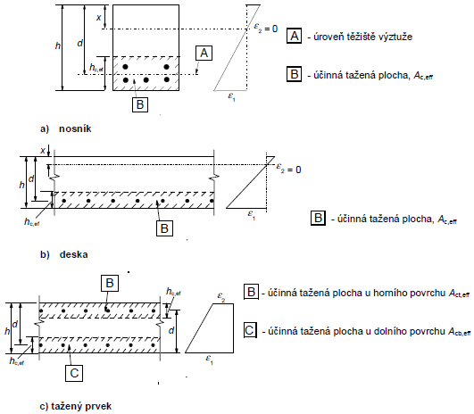
Ac,eff účinná plocha taženého betonu obklopující betonářskou nebo předpínací výztuž o výšce hc,ef  (viz obrázek 7.1)


hc,ef je menší z hodnot:


  • 2,5(h - d)

  • (h - x)/3

  • h/2


Obrázek 7.1 - Účinná tažená plocha (typické případy)
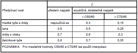


je poměr pevnosti v soudržnosti předpínací a betonářské výztuže podle tabulky 6.2 v 6.8.2:


k1 je součinitel, kterým se zohledňují vlastnosti soudržné výztuže:

= 0,8 pro pruty s velkou soudržností;

= 1,6 pro pruty s hladkým povrchem (např. předpínací vložky);


k2 je součinitel, kterým se zohledňuje rozdělení poměrného přetvoření:

= 0,5 pro ohyb;

= 1,0 pro prostý tah.

Pro případy mimostředného tahu nebo pro místní oblasti se mají použít mezilehlé hodnoty k2, které se vypočítají podle následujícího vztahu:

k2 = (e1 + e2)/2e1

kde e1 je větší a e2 menší tahové poměrné přetvoření na okrajích vyšetřovaného průřezu,stanovené v průřezu, který je celý oslaben trhlinou.


Hodnoty k3 a k4, které se použijí v příslušném státě, lze nalézt v národní příloze. V ČR platí doporučené hodnoty (viz NA 2.74):


k3 = 3,400


k4 = 0,425.


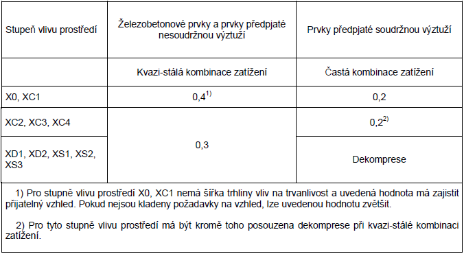
Tabulka 7.1N - Doporučené hodnoty wmax (mm)


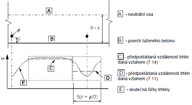
Obrázek 7.2 - Šířka trhliny na povrchu betonu v závislosti na vzdálenosti od prutu


Vnitřní síly na mezi vzniku trhlin
EuroCode - EN 1992-1-1 -
Autor: Design Forms s.r.o.
Vytvořen: 02.11.2016
Naposledy upraven: 02.11.2016
Popis:
Výpočet sil na mezi vzniku trhlin
Anotace:

Šablona počítá kombinaci vnitřních sil, která způsobuje limitní namáhání betonu v tahu.


Šablona vezme zadanou kombinaci {N, My, Mz} a iteračním způsobem najde koeficient "R" tak, aby platilo, že kombinace {N, R*My, R*Mz} způsobí limitní tahové namáhání betonu.


Zadaná normálová tedy není měněna. Ohybové momenty jsou lineárně zvětšeny/zmenšeny tak, aby bylo dosaženo limitního namáhání betonu.


Posouzení podélné a smykové výztuže
EuroCode - EN 1992-1-1 -
Autor: Design Forms s.r.o.
Vytvořen: 09.11.2016
Naposledy upraven: 09.11.2016
Popis:
Posouzení podélné a smykové výztuže
Anotace:
Posouzení podélné a smykové výztuže na obecném průřezu.

▶ EuroCode - EN 1995-1-1
Posouzení vzpěru
EuroCode - EN 1995-1-1 -
Autor: Design Forms s.r.o.
Vytvořen: 19.08.2016
Naposledy upraven: 29.08.2016
Popis:
Posouzení vzpěru dřevěného prutu
Anotace:

Hodnota součinitele bc se má uvažovat následovně (článek 6.3.2):


Materiál bc
Rostlé dřevo 0,20
Lepené dřevo a LVL 0,10


Hodnota součinitele km se má uvažovat následovně (článek 6.1.6):


Materiál Průřez km
Rostlé dřevo, lepené lamelové dřevo, LVL obdélníkové průřezy 0,70
ostatní průřezy 1,00
Ostatní í konstrukční výrobky na bázi dřeva všechny průřezy 1,00


Tabulka 6.1 - Účinná délka jako poměr rozpětí


Posouzení kombinace N+My+Mz
EuroCode - EN 1995-1-1 -
Autor: Design Forms s.r.o.
Vytvořen: 19.08.2016
Naposledy upraven: 29.08.2016
Popis:
Posouzení dřevěného prutu na kombinaci N + My + Mz
Anotace:

Hodnota součinitele bc se má uvažovat následovně (článek 6.3.2):


Materiál bc
Rostlé dřevo 0,20
Lepené dřevo a LVL 0,10


Hodnota součinitele km se má uvažovat následovně (článek 6.1.6):


Materiál Průřez km
Rostlé dřevo, lepené lamelové dřevo, LVL obdélníkové průřezy 0,70
ostatní průřezy 1,00
Ostatní í konstrukční výrobky na bázi dřeva všechny průřezy 1,00


Tabulka 6.1 - Účinná délka jako poměr rozpětí


Posouzení tahu
EuroCode - EN 1995-1-1 -
Autor: Design Forms s.r.o.
Vytvořen: 19.08.2016
Naposledy upraven: 29.08.2016
Popis:
Posouzení dřevěného prutu na tah
Anotace:
Anet - plocha oslabeného průřezu (např. otvory pro svorníky, zářezy apod)

Spoj dřevo - ocel
EuroCode - EN 1995-1-1 -
Autor: Design Forms s.r.o.
Vytvořen: 19.08.2016
Naposledy upraven: 07.11.2016
Popis:
Posouzení spoje ocel - dřevo
Anotace:


Image 8.3 - Kind of breaches for connection steel - timber


Image 8.4 - Definition t1, t2


a) on shear plane; b) two shear planes


Image 8.5 - Covering nails


Image 8.7 - Distances from ends and edges


a) distances paraller with grain in the line and paraller to grain between lines; b) distances from ends and edges


(1) - loaded end

(2) - un-loaded end

(3) - loaded edge

(4) - un-loaded edge

1 - connection

2 - fibers direction


▶ Invariant - Statics
Statika prostého nosníku
Invariant - Statics -
Autor: Design Forms s.r.o.
Vytvořen: 20.08.2016
Naposledy upraven: 29.08.2016
Popis:
Výpočet průběhu ohybového momentu a smykové síly na prostém nosníku
Anotace:
Bending moment and shear force on simple beam

Statika konzoly
Invariant - Statics -
Autor: Design Forms s.r.o.
Vytvořen: 29.08.2016
Naposledy upraven: 29.08.2016
Popis:
Průběh ohybového momenty a posouvající síly na konzole
Anotace:
Statics of console

Parametry obecného průřezu
Invariant - Statics -
Autor: Design Forms s.r.o.
Vytvořen: 19.09.2016
Naposledy upraven: 19.09.2016
Popis:
Výpočet parametrů obecného průřezu
Anotace:
Calculate parameters of general cross section

▶ EuroCode - EN 1996-1-1
Posouzení zdiva v tlaku
EuroCode - EN 1996-1-1 -
Autor: Design Forms s.r.o.
Vytvořen: 23.08.2016
Naposledy upraven: 29.08.2016
Popis:
Posouzení zdiva v tlaku, včetně vlivu vzpěru
Anotace:
Check of masonry in compression

Posouzení zdiva se soustředěným zatížením
EuroCode - EN 1996-1-1 -
Autor: Design Forms s.r.o.
Vytvořen: 23.08.2016
Naposledy upraven: 29.08.2016
Popis:
Posouzení zděné stěny na koncentrované zatížení
Anotace:
Check of masonry in concentrated compression

Posouzení stěny zatížené boční silou
EuroCode - EN 1996-1-1 -
Autor: Design Forms s.r.o.
Vytvořen: 24.08.2016
Naposledy upraven: 29.08.2016
Popis:
Posouzení zdiva zatíženého boční silou
Anotace:
Check of masonry loaded by lateral force

▶ EuroCode - EN 1997-1-1
Geostatické napětí
EuroCode - EN 1997-1-1 -
Autor: Design Forms s.r.o.
Vytvořen: 19.09.2016
Naposledy upraven: 19.09.2016
Popis:
Výpočet geotechnických napětí
Anotace:
Calculation of geotechnic stress

Výpočet únosnosti vrtané piloty dle ULS
EuroCode - EN 1997-1-1 -
Autor: Design Forms s.r.o.
Vytvořen: 22.09.2016
Naposledy upraven: 22.09.2016
Popis:
Výpočet únosnosti vrtané piloty dle Masopustovy teorie (ČSN 73 1002)
Anotace:
Bearing capacity of bored piles according to Masopust theory (ČSN 73 1002)

Únosnost skupiny pilot
EuroCode - EN 1997-1-1 -
Autor: Design Forms s.r.o.
Vytvořen: 22.09.2016
Naposledy upraven: 22.09.2016
Popis:
Výpočet únosnosti skupiny pilot dle Masopustovy teorie (ČSN 73 1002)
Anotace:
Bearing capacity of pile group according to the Masopust theory (ČSN 73 1002)

Únosnost samostatné mikropiloty
EuroCode - EN 1997-1-1 -
Autor: Design Forms s.r.o.
Vytvořen: 26.09.2016
Naposledy upraven: 31.07.2017
Popis:
Únosnost mikropiloty
Anotace:

Výpočet únosnosti mikropiloty podľa Masopusta (2004) 


Únosnosť koreňovej časti je daná súčtom únosnosti na plášti a päte mikropilóty.
Únosnosť na päte tlačenej mikropilóty sa zanedbáva, ak koreň mikropilóty nie je
votknutý (popr. opretý) do hornín R1 až R3.


Umv,d = Ums,d + Ump,d


  • Umv,d koreňová únosnosť mikropilóty

  • Ums,d únosnosť na plášti koreňa mikropilóty

  • Ump,d únosnosť na päte tlačenej mikropilóty


Ums,d = π · d · l · τi
· mz


  • d priemer koreňa

  • l dĺžka koreňa

  • τi priemerná medzná hodnota plášťového trenia (Tab. 3-5) 

  • mz koeficient závislý na druhu zaťaženia (=1.0 pro tlak, =0.8 pro tah)


Ump,d = π · d
2
/(4 · Rd)


  • d priemer koreňa

  • Rd únosnosť na päte pre skalné horniny R1 – R3  (Tab. 3-7)


Posouzení únosnosti základové patky
EuroCode - EN 1997-1-1 -
Autor: Design Forms s.r.o.
Vytvořen: 07.11.2016
Naposledy upraven: 09.11.2016
Popis:
Posouzení únosnosti základové patky
Anotace:

Posouzení únosnosti základové patky.


Posudky:


  • Posouzení únosnosti základové spáry v odvodněných podmínkách

  • Posouzení usmyknutí v základové spáře v odvodněných podmínkách

  • Posouzení únosnosti základové spáry v neodvodněných podmínkác

  • Posouzení usmyknutí v základové spáře v neodvodněných podmínkách


Posouzení stability gravitační stěny
EuroCode - EN 1997-1-1 -
Autor: Design Forms s.r.o.
Vytvořen: 05.12.2016
Naposledy upraven: 05.12.2016
Popis:
Posouzení stability gravitační zdi
Anotace:

Calculation of earth pressure coefficients and earth pressures


  • Horizontal earth pressure coefficients are calculated according to EN 1997-1 Annex C 2. By using this method, it is possible to calculate coefficients of horizontal active and passive earth pressure for variable soil conditions, terrain inclination, construction inclination and soil strength parameters.

    • Partial coefficient of horizontal earth pressure for vertical loading on the surface:


(1)


    • Partial coefficient of horizontal earth pressure for cohesion


(2)


    • Partial coefficient of horizontal earth pressure for soil weight 


(3)


  • In the formulas (1) - (3), b is the angle from the horizontal to the soil surface (positive when the soil surface rises away from the wall),Q is the angle between the vertical and the wall direction (positive when the soil overhangs the wall), f is the angle of internal friction and KN is the coefficient of the normal earth pressure acting on the wall from a unit pressure normal to the surface. Further detail can be found in EN 1997-1 Annex C 2.


  • The inclusion of the mobilisation of earth pressure in front of the wall is optional. Height of the soil in front of the wall hp is an input parameter. User has 2 possible alternatives:

    • No earth pressure in front of the wall is taken into account,


    • 1/2 passive earth pressure + 1/2 earth pressure at rest 


Check wall stability


  • Degree of utilization in the case of toppling is calculated according to the formula (5), where MED,dst and MED,stb are destabilizing and stabilizing moment around the construction toe. 


(5)

Safety factors according to EN 1997


  • It is possible to use 9 different partial factors:

    • gG- partial factor of safety for the unfavorable permanent  load (Action),

    • gG,fav- partial factor of safety for the favorable permanent  load (Action),

    • gload - partial factor of safety for the surface load - for higher versatility treated as separate factor (Action),

    • gRh- partial factor of safety for sliding resistance (Resistance),

    • gRv- partial factor of safety for bearing resistance (Resistance),

    • gangle- partial factor of safety for the angle of internal friction (Material),

    • gcohesion- partial factor of safety for the cohesion (Material),

    • gweight,soil- partial factor of safety for the soil unit weight (Material), 

    • gweight,wall- partial factor of safety for the wall unit weight (Material).


  • Appropriate combination of partial factors can be chosen for required design approach.

  • Earth pressure in front of the wall is taken as favorable action.


Posouzení únosnosti lanové kotvy
EuroCode - EN 1997-1-1 -
Autor: Design Forms s.r.o.
Vytvořen: 13.12.2016
Naposledy upraven: 13.12.2016
Popis:
Únosnost lanové kotvy
Anotace:

Parametry lanových kotev


Typ lana 15,5/1620 15,5/1800 15,7/1770
Nominální průměr [mm] 15,5 15,5 15,7
Nominální plocha průřezu [mm2] 141,5 141,5 150,0
Síla / napětí
limitní Fm [kN] 229,2 255 265,5
fp [MPa] 1620 1800 1770
na mezi kluzu 0,2% Fp0,2 [kN] 194,8 217 235,5
fp0,2 [MPa] 1377 1532 1570
na mezi kluzu 0,1% Fp0,1 [kN] - 178 -
fp0,1 [MPa] - 1620 -
Duktilita [%] 3,0 3,5 3,5
Youngův modul [GPa] 200 ± 10 % 200 ± 10 % 195
Hmotnost [kg/bm] 1,12 1,12 1,15
Nominální nosnost lana [kN] 120 140 142


Únosnost tyčové kotvy
EuroCode - EN 1997-1-1 -
Autor: Design Forms s.r.o.
Vytvořen: 15.12.2016
Naposledy upraven: 15.12.2016
Popis:
Únosnost tyčové kotvy
Anotace:

Parametry kotev


Parametry kotev byly převzaty z tabulek výrobce


Parametr Anchor

CPS
Anchor Dywidag
Steel 835/1030 Steel 1080/1230
Ø32 Ø26,5 Ø32 Ø36 Ø26,5 Ø32 Ø36
Jmenovitý průměr[mm] 32 26,5 32 36 26,5 32 36
Stoupání závitu[mm] 17 13 16 18 13 16 18
Plocha průřezu[mm2] 777 551 804 1018 551 804 1018
Hmotnost [kg/m] 6,78 4,48 6,53 8,27 4,48 6,53 8,27
Mezní síla [kN] 776 568 828 1049 678 989 1252
Napětí na mezi pevnosti [MPa] 1000 1030 1230
Návrhová únosnost [kN] 415 284 414 524 339 495 626


▶ EuroCode - EN 1991
Zatížení větrem
EuroCode - EN 1991 - Wind
Autor: Design Forms s.r.o.
Vytvořen: 10.01.2017
Naposledy upraven: 22.02.2017
Popis:
Basic wind speed and pressure
Anotace:

Dialogue


National annex selector


Combobox "National Annex" is used for selecting proper annex for calculation of the wind load.

Wind load requires selection the national annex, because in Standard EN is many national decisions possible.

For explanation of the National annex parameters related to wind load select national annex from the list below.

BS National Annex


ČSN National Annex


DIN National Annex


ELOT National Annex


IS National Annex


LU National Annex


NBN National Annex


NEN National Annex


NF National Annex


ÖNORM National Annex


PN National Annex


SFS National Annex


SIST National Annex


SR National Annex


STN National Annex


General properties


General properties are similar to all wind load forms.

Checkbox "Print headline" represent official name for calculation. User can change it by uncheck "Print headline" and check "Print user defined headline" and write his own headline into appropriate string line.

Wind parameters


This group of parameters depend on selected national annex.

BS National Annex


Wind azimuth in degrees is used in calculation of directional factor cdir. Wind azimuth is from 0 ° to 360 ° from North in a clockwise direction.

Fundamental value of the basic wind velocity from the map vb,map in metres per second. Map can be found in National annex page, Figure NA.1

Turbulence intensity from the diagram Iv(z)map. Diagram can be found in National annex page, Figure NA.5

Turbulence intensity factor from the diagram kI,T. Diagram can be found in National annex page, Figure NA.6

CSN National Annex


Wind region is from I to V according map of the wind regions. Map can be found in National annex page.

DIN National Annex


Wind region is from WZ1 to WZ4 according map of the wind regions. Map can be found in National annex page.

ELOT National Annex


No special wind parameters are necessary for ELOT National annex.

IS National Annex


Wind azimuth in degrees is used in calculation of directional factor cdir. Wind azimuth is from 0 ° to 360 ° from North in a clockwise direction.

Fundamental value of the basic wind velocity from the map vb,map in metres per second. Map can be found in National annex page, Figure NA.1

Turbulence intensity from the diagram Iv(z)map. Diagram can be found in National annex page, Figure NA.5

Turbulence intensity factor from the diagram kI,T. Diagram can be found in National annex page, Figure NA.6

LU National Annex


No special wind parameters are necessary for LU National annex.

NBN National Annex


Wind region is from 1 to 4 according map of the wind regions. Map can be found in National annex page.

Wind azimuth in degrees is used in calculation of directional factor cdir. Wind azimuth is from 0 ° to 360 ° from North in a clockwise direction.

NEN National Annex


Wind region is from I to III according map of the wind regions. Map can be found in National annex page.

NF National Annex


Wind region is from 1 to 4 according map of the wind regions. Map can be found in National annex page.

Direction zone is from 1 to 3 according map of the wind directions. Map can be found in National annex page.

Wind azimuth in degrees is used in calculation of directional factor cdir. Wind azimuth is from 0 ° to 360 ° from North in a clockwise direction.

ONORM National Annex


According selected state in Austria can be selected the municipality which is the nearest to the construction site. Table of all possible municipalities can be found in National annex page.

PN National Annex


Wind region is from 1 to 3 according map of the wind regions. Map can be found in National annex page.

Wind azimuth in degrees is used in calculation of directional factor cdir. Wind azimuth is from 0 ° to 360 ° from North in a clockwise direction.

SFS National Annex


Wind regions in SFS are defined as:

a) Mainland in the entire country

b) Sea areas: open sea, scattered islands out in the open sea

c) In Lappland: at the top of mountains

d) In Lappland: at the bottom of mountains

SIST National Annex


Wind region is from 1 to 3 according map of the wind regions. Map can be found in National annex page.

SR National Annex


Fundamental value of the basic wind velocity from the map in metres per second. Map can be found in National annex page.

STN National Annex


Wind region is from I to II according map of the wind regions. Map can be found in National annex page. For higher altitude, two more regions are available.

Terrain parameters


Standard values exist. Different parameters can be defined in National annex.

Standard values


Terrain category is standardly from 0 to IV. Different terrain categories can be defined in National annex page.

Checkbox "Calculate orographic factor" allows calculation of orographic factor. In National annex can be specified procedure to calculate orographic factor. Standard procedure is in Annex A.3.

BS and IS National Annexes


Three terrain categories are available in BS. Sea, Country and town. More information about BS terrain categories can be found in National annex page.

Roughness factor cr,diag is determined from the diagram Figure NA.3 Diagram can be found in National annex page.

Roughness correction factor cr,T is determined from the diagram Figure NA.4 Diagram can be found in National annex page.

Exposure factor ce,diag is determined from the diagram Figure NA.7 Diagram can be found in National annex page.

Exposure correction factor ce,T is determined from the diagram Figure NA.8 Diagram can be found in National annex page.

Distance upwind to shoreline in km is used in the diagrams mentioned above.

Distance inside town terrain in km is used in the diagrams mentioned above.

Checkbox "Calculate orographic factor" is used, if orographic factor should be calculated according Annex A.3

Orographic factor - Recommended Annex A.3 input


Orographic terrain can be Cliffs and escarpments or Hills and ridges.

Horizontal distance of the site from the top of the crest in metres. Use positive value for downwind slope and negative value for upwind slope.

Effective height of the hill in metres.

Actual length of the upwind slope in the wind direction in metres.

Actual length of the downwind slope in the wind direction in metres.

Construction parameters


Construction parameters depend on selected National annex.

Reference height above terrain in metres is the most important parameter. It define in which height is calculated wind pressure. If is necessary to calculate wind pressure in more heights, repeat calculation with propper height z.

Checkbox "Temporary structure or execution phase" is used, if season construction is designed and season factor is necessary.

Checkbox "Use accurate information about the obstructions height" is used, if average height of neighbouring structures is know in Terrain category IV.

Calculation


Basic values


Basic wind velocity is calculated as vb = cdir • cseason • vb,0 in metres per second.

Fundamental value of the basic wind velocity vb,0 is defined in selected National annex in metres per second. 

Directional factor cdir = 1.0 in standard. Different value can be defined in National annex page.

Season factor cseason = 1,0 in standard. A different value can be defined in National annex page.

Reference height above terrain in metres is the height in which is peak velocity pressure calculated. It is one of the most important values in the calculation.

Mean wind velocity


For DIN and ONORM are this and follows paragraphs unavailable. Instead of it, there is block "Wind parameters" where is calculation of wind parameters according National annex.

Mean wind velocity in metres per second is calculated as vm = cr • cO • vb

Terrain roughness factor cr depends on height above ground level and selected terrain category.

 for zmin ≤ z ≤ zmax

 for z ≤ zmin

where:

z0 is the roughness length

kr is terrain factor


where:

z0,II = 0,05 (terrain category II, Table 4.1)

zmin is the minimum height defined in Table 4.1

zmax is to be taken as 200 m


Table 4.1 - Terrain categories and terrain parameters


Terrain category z0

[m]
zmin

[m]
0   Sea or coastal area exposed to the open sea 0,003 1
I   Lakes or flat and horizontal area with negligible vegetation and without obstacles 0,01 1
II   Area with low vegetation such as grass and isolated obstacles (trees, buildings) with separations of at least 20 obstacle heights 0,05 2
III   Area with regular cover of vegetation or buildings or with isolated obstacles with separations of maximum 20 obstacle heights (such as villages, suburban terrain, permanent forest) 0,3 5
IV   Area in which at least 15 % of the surface is covered with buildings and their average height exceeds 15 m 1,0 10


Orography factor cO = 1 in normal cases.

Where orography increases wind velocities by more than 5 % the effects should be taken into account using the orography factor. Recommended procedure is given in Annex A.3. Different procedure can be specified in National annex.

Orographic factor - Recommended procedure according to Annex A.3


1) Calculation of the upstream slope


2) Decision if the calculation of orography factor is necessary

The effects of orography should be taken into account in the following situations:

a) For sites on upwind slopes of hills and ridges:

- where 0,05 < Φ ≤ 0,3 and |x| ≤ Lu / 2

b) For sites on downwind slopes of hills and ridges:

- where Φ < 0,3 and x < Ld / 2

- where Φ ≥ 0,3 and x < 1,6 • H

c) For sites on upwind slopes of cliffs and escarpments:

- where 0,05 < Φ ≤ 0,3 and |x| ≤ Lu / 2

d) For sites on downwind slopes of cliffs and escarpments:

- where Φ < 0,3 and x < 1,5 • Le

- where Φ ≥ 0,3 and x < 5 • H


3) Orography factor is than defined by:


Orographic factor Limits
cO = 1 Φ < 0,05
cO = 1 + 2 • s • Φ 0,05 < Φ < 0,3
cO = 1 + 0,6 • s Φ > 0,3

where:

s is the orographic location factor

Φ is the upwind slope H/Lu in the wind direction

Le is the effective length of the upwind slope

Lu is the actual length of the upwind slope in the wind direction

Ld is the actual length of the downwind slope in the wind direction

H is the effective height of the feature

x is the horizontal distance of the site from the top of the crest

z is the vertical distance from the ground level of the site


Values of the effective length Le


Type of slope (Φ = H/Lu)
Shallow (0,05 < Φ < 0,3) Steep (Φ > 0,3)
Le = Lu Le = H/0,3


Orographic location factor s for cliffs and escarpments


Orographic location factor s for hills and ridges


a) upwind section for all orography

For the ranges


take


where


when


take

s = 0

b) downwind section for cliffs and escarpments

For the ranges


take


where


For the range


interpolate between values for


when


use the values for


when


take

s = 0

c) downwind section for hills and ridges

For the ranges


take


where


when


take

s = 0

Displacement height - Recommended procedure according Annex A.5


For building in Terrain category IV, can be reference height of building on the upwind side lowered by displacement height hdis due to closely spaced buildings and other obstructions.


hdis = min(0,8 • have; 0,6 • h) for x ≤ 2 • have

hdis = min(1,2 • have - 0,2 • x; 0,6 • h) for 2 • have ≤ x ≤ 6 • have

hdis = 0 for x ≥ 6 • have

Peak velocity pressure


Function for calculation peak velocity pressure at height z can be defined in National annex. Recommended formula is:


where:

ρ is the air density, which depends on the altitude, temperature and barometric pressure. ρ can be defined in National annex, recommended value is 1,25 kg/m3.

vm is mean wind velocity

Iv is turbulence intensity. It can be defined in National annex. Recommended formula is:

 for zmin ≤ z ≤ zmax

Iv = Iv(zmin) for z ≤ zmin

kI is turbulence factor. It may be defined in National annex. Recommended value is 1,0

Explanation of symbols


A - Construction site altitude above sea level [m]

AE1 - Altitude above sea level in east direction in 500 m from the site [m]

AE2 - Altitude above sea level in east direction in 1000 m from the site [m]

AN1 - Altitude above sea level in north direction in 500 m from the site [m]

AN2 - Altitude above sea level in north direction in 1000 m from the site [m]

AO1 - Altitude above sea level in west direction in 500 m from the site [m]

AO2 - Altitude above sea level in west direction in 1000 m from the site [m]

AS1 - Altitude above sea level in south direction in 500 m from the site [m]

AS2 - Altitude above sea level in south direction in 1000 m from the site [m]

cdir - Directional factor

ce,diag - Exposure factor from the diagram

ce,T - Exposure correction factor from the diagram

cO - Orography factor

cr,diag - Roughness factor from the diagram

cr,T - Roughness correction factor from the diagram

cr - Roughness factor

cseason - Season factor

Dir - Wind azimuth [°]

DisShore - Distance upwind to shoreline [km]

DisTown - Distance inside town terrain [km]

h - Height of the construction [m]

H - Effective height of the hill [m]

have - Average height of buildings in the city [m]

hdis - Height in the distance in terrain category IV [m]

Iv(z)flat - Turbulence intensity from the diagram

Iv - Turbulence intensity

kI,T - Turbulence intensity factor from the diagram

Ld - Actual length of the downwind slope in the wind direction [m]

Lu - Actual length of the upwind slope in the wind direction [m]

qb,0 - Fundamental value of basic wind pressure [kN/m2]

qb - Basic wind pressure [kN/m2]

qp - Peak velocity pressure [kN/m2]

T - The absolute air temperature at the load condition [K]

vb,0,CHMI - Fundamental value of the basic wind velocity according CHMI [m/s]

vb,0 - Fundamental value of the basic wind velocity [m/s]

vb,map - Fundamental value of the basic wind velocity from the map [m/s]

vb - Basic wind velocity [m/s]

vm - Mean wind velocity [m/s]

vp - Gust wind velocity [m/s]

x - Horizontal distance of the site from the top of the crest [m]

xDis - Site distance from the other building [m]

z - Reference height above terrain [m]

z0 - Roughness length [m]

zmin - Minimum height [m]

ρ - Air density [kg/m3]

Zatížení větrem - pultové střechy
EuroCode - EN 1991 - Wind
Autor: Design Forms s.r.o.
Vytvořen: 11.01.2017
Naposledy upraven: 22.02.2017
Popis:
Wind load on the monopitch roofs
Anotace:

Dialogue


National annex selector


Combobox "National Annex" is used for selecting proper annex for calculation of the wind load.

Wind load requires selecion the national annex, because in Standard EN is many national decisions possible.

For explanation of the National annex parameters related to wind load select national annex from the list below.

BS National Annex


ČSN National Annex


DIN National Annex


ELOT National Annex


IS National Annex


LU National Annex


NBN National Annex


NEN National Annex


NF National Annex


ÖNORM National Annex


PN National Annex


SFS National Annex


SIST National Annex


SR National Annex


STN National Annex


General properties


General properties are similar to all wind load forms.

Checkbox "Print headline" represent official name for calculation. User can change it by uncheck "Print headline" and check "Print userdefined headline" and write his own headline into appropriate string line.

Wind parameters


This group of parameters depend on selected national annex.

BS National Annex


Wind azimuth in degrees is used in calculation of directional factor cdir. Wind azimuth is from 0 ° to 360 ° from North in a clockwise direction.

Fundamental value of the basic wind velocity from the map vb,map in metres per second. Map can be found in National annex page, Figure NA.1

Turbulence intensity from the diagram Iv(z)map. Diagram can be found in National annex page, Figure NA.5

Turbulence intensity factor from the diagram kI,T. Diagram can be found in National annex page, Figure NA.6

CSN National Annex


Wind region is from I to V according map of the wind regions. Map can be found in National annex page.

DIN National Annex


Wind region is from WZ1 to WZ4 according map of the wind regions. Map can be found in National annex page.

ELOT National Annex


No special wind parameters are necessary for ELOT National annex.

IS National Annex


Wind azimuth in degrees is used in calculation of directional factor cdir. Wind azimuth is from 0 ° to 360 ° from North in a clockwise direction.

Fundamental value of the basic wind velocity from the map vb,map in metres per second. Map can be found in National annex page, Figure NA.1

Turbulence intensity from the diagram Iv(z)map. Diagram can be found in National annex page, Figure NA.5

Turbulence intensity factor from the diagram kI,T. Diagram can be found in National annex page, Figure NA.6

LU National Annex


No special wind parameters are necessary for LU National annex.

NBN National Annex


Wind region is from 1 to 4 according map of the wind regions. Map can be found in National annex page.

Wind azimuth in degrees is used in calculation of directional factor cdir. Wind azimuth is from 0 ° to 360 ° from North in a clockwise direction.

NEN National Annex


Wind region is from I to III according map of the wind regions. Map can be found in National annex page.

NF National Annex


Wind region is from 1 to 4 according map of the wind regions. Map can be found in National annex page.

Direction zone is from 1 to 3 according map of the wind directions. Map can be found in National annex page.

Wind azimuth in degrees is used in calculation of directional factor cdir. Wind azimuth is from 0 ° to 360 ° from North in a clockwise direction.

ONORM National Annex


According selected state in Austria can be selected the municipality which is the nearest to the construction site. Table of all possible municipalities can be found in National annex page.

PN National Annex


Wind region is from 1 to 3 according map of the wind regions. Map can be found in National annex page.

Wind azimuth in degrees is used in calculation of directional factor cdir. Wind azimuth is from 0 ° to 360 ° from North in a clockwise direction.

SFS National Annex


Wind regions in SFS are defined as:

a) Mainland in the entire country

b) Sea areas: open sea, scattered islands out in the open sea

c) In Lappland: at the top of mountains

d) In Lappland: at the bottom of mountains

SIST National Annex


Wind region is from 1 to 3 according map of the wind regions. Map can be found in National annex page.

SR National Annex


Fundamental value of the basic wind velocity from the map in metres per second. Map can be found in National annex page.

STN National Annex


Wind region is from I to II according map of the wind regions. Map can be found in National annex page. For higher altitude, two more regions are availabile.

Terrain parameters


Standard values exist. Different parameters can be defined in National annex.

Standard values


Terrain category is standardly from 0 to IV. Different terrain categories can be defined in National annex page.

Checkbox "Calculate orographic factor" allows calculation of orographic factor. In National annex can be specified procedure to calculate orographic factor. Standard procedure is in Annex A.3.

BS and IS National Annexes


Three terrain categories are availabile in BS. Sea, Country and town. More informations about BS terrain categories can be found in National annex page.

Roughness factor cr,diag is determined from the diagram Figure NA.3 Diagram can be found in National annex page.

Roughness correction factor cr,T is determined from the diagram Figure NA.4 Diagram can be found in National annex page.

Exposure factor ce,diag is determined from the diagram Figure NA.7 Diagram can be found in National annex page.

Exposure correction factor ce,T is determined from the diagram Figure NA.8 Diagram can be found in National annex page.

Distance upwind to shoreline in km is used in the diagrams mentioned above.

Distance inside town terrain in km is used in the diagrams mentioned above.

Checkbox "Calculate orographic factor" is used, if orographic factor should be calculated according Annex A.3

Orographic factor - Recommended Annex A.3 input


Orographic terrain can be Cliffs and escarpments or Hills and ridges.

Horizontal distance of the site from the top of the crest in metres. Use positive value for downwind slope and negative value for upwind slope.

Effective height of the hill in metres.

Actual length of the upwind slope in the wind direction in metres.

Actual length of the downwind slope in the wind direction in metres.

Construction parameters


Construction parameters depend on selected National annex.

Reference height above terrain in metres is the most important parameter. It define in which height is calculated wind pressure. If is necessary to calculate wind pressure in more heights, repeat calculation with propper height z.

Checkbox "Temporary structure or execution phase" is used, if season construction is designed and season factor is necessary.

Checkbox "Use accurate informations about the obstructions height" is used, if average height of neighbluring structures is know in Terrain category IV.

Calculation


Basic values


Basic wind velocity is calculated as vb = cdir • cseason • vb,0 in metres per second.

Fundamental value of the basic wind velocity vb,0 is defined in selected National annex in metres per second. 

Directional factor cdir = 1.0 in standard. Different value can be defined in National annex page.

Season factor cseason = 1,0 in standard. Different value can be defined in National annex page.

Reference height above terrain in metres is the height in which is peak velocity pressure calculated. It is one of the most important values in the calculation.

Mean wind velocity


For DIN and ONORM are this and follows paragraphs unavailabile. Instead of it, there is block "Wind parameters" where is calculation of wind parameters according National annex.

Mean wind velocity in metres per second is calculated as vm = cr • cO • vb

Terrain roughness factor cr depends on height above ground level and selected terrain category.

 for zmin ≤ z ≤ zmax

 for z ≤ zmin

where:

z0 is the roughness length

kr is terrain factor


where:

z0,II = 0,05 (terrain category II, Table 4.1)

zmin is the minimum height defined in Table 4.1

zmax is to be taken as 200 m


Table 4.1 - Terrain categories and terrain parameters


Terrain category z0

[m]
zmin

[m]
0   Sea or coastal area exposed to the open sea 0,003 1
I   Lakes or flat and horizontal area with negligible vegetation and without obstacles 0,01 1
II   Area with low vegetation such as grass and isolated obstacles (trees, buildings) with separations of at least 20 obstacle heights 0,05 2
III   Area with regular cover of vegetation or buildings or with isolated obstacles with separations of maximum 20 obstacle heights (such as villages, suburban terrain, permanent forest) 0,3 5
IV   Area in which at least 15 % of the surface is covered with buildings and their average height exceeds 15 m 1,0 10


Orography factor cO = 1 in normal cases.

Where orography increases wind velocities by more than 5 % the effects should be taken into account using the orography factor. Recommended procedure is given in Annex A.3. Different procedure can be specified in National annex.

Orographic factor - Recommended procedure according Annex A.3


1) Calculation of the upstream slope


2) Decision if the calculation of orography factor is necessary

The effects of orography should be taken into account in the following situations:

a) For sites on upwind slopes of hills and ridges:

- where 0,05 < Φ ≤ 0,3 and |x| ≤ Lu / 2

b) For sites on downwind slopes of hills and ridges:

- where Φ < 0,3 and x < Ld / 2

- where Φ ≥ 0,3 and x < 1,6 • H

c) For sites on upwind slopes of cliffs and escarpments:

- where 0,05 < Φ ≤ 0,3 and |x| ≤ Lu / 2

d) For sites on downwind slopes of cliffs and escarpments:

- where Φ < 0,3 and x < 1,5 • Le

- where Φ ≥ 0,3 and x < 5 • H


3) Orography factor is than defined by:


Orographic factor Limits
cO = 1 Φ < 0,05
cO = 1 + 2 • s • Φ 0,05 < Φ < 0,3
cO = 1 + 0,6 • s Φ > 0,3

where:

s is the orographic location factor

Φ is the upwind slope H/Lu in the wind direction

Le is the effective length of the upwind slope

Lu is the actual length of the upwind slope in the wind direction

Ld is the actual length of the downwind slope in the wind direction

H is the effective height of the feature

x is the horizontal distance of the site from the top of the crest

z is the vertical distance from the ground level of the site


Values of the effective length Le


Type of slope (Φ = H/Lu)
Shallow (0,05 < Φ < 0,3) Steep (Φ > 0,3)
Le = Lu Le = H/0,3


Orographic location factor s for cliffs and escarpments


Orographic location factor s for hills and ridges


a) upwind section for all orography

For the ranges


take


where


when


take

s = 0

b) downwind section for cliffs and escarpments

For the ranges


take


where


For the range


interpolate between values for


when


use the values for


when


take

s = 0

c) downwind section for hills and ridges

For the ranges


take


where


when


take

s = 0

Displacement height - Recommended procedure according Annex A.5


For building in Terrain category IV, can be reference height of building on the upwind side lowered by displacement height hdis due to closely spaced buildings and other obstructions.


hdis = min(0,8 • have; 0,6 • h) for x ≤ 2 • have

hdis = min(1,2 • have - 0,2 • x; 0,6 • h) for 2 • have ≤ x ≤ 6 • have

hdis = 0 for x ≥ 6 • have

Peak velocity pressure


Function for calculation peak velocity pressure at height z can be defined in National annex. Recommended formula is:


where:

ρ is the air density, which depends on the altitude, temperature and barometric pressure. ρ can be defined in National annex, recommended value is 1,25 kg/m3.

vm is mean wind velocity

Iv is turbulence intensity. It can be defined in National annex. Recommended formula is:

 for zmin ≤ z ≤ zmax

Iv = Iv(zmin) for z ≤ zmin

kI is turbulence factor. It may be defined in National annex. Recommended value is 1,0

Explanation of symbols


A - Construction site altitude above sea level [m]

AE1 - Altitude above sea level in east direction in 500 m from the site [m]

AE2 - Altitude above sea level in east direction in 1000 m from the site [m]

AN1 - Altitude above sea level in north direction in 500 m from the site [m]

AN2 - Altitude above sea level in north direction in 1000 m from the site [m]

AO1 - Altitude above sea level in west direction in 500 m from the site [m]

AO2 - Altitude above sea level in west direction in 1000 m from the site [m]

AS1 - Altitude above sea level in south direction in 500 m from the site [m]

AS2 - Altitude above sea level in south direction in 1000 m from the site [m]

cdir - Directional factor

ce,diag - Exposure factor from the diagram

ce,T - Exposure correction factor from the diagram

cO - Orography factor

cr,diag - Roughness factor from the diagram

cr,T - Roughness correction factor from the diagram

cr - Roughness factor

cseason - Season factor

Dir - Wind azimuth [°]

DisShore - Distance upwind to shoreline [km]

DisTown - Distance inside town terrain [km]

h - Height of the construction [m]

H - Effective height of the hill [m]

have - Average height of buildings in the city [m]

hdis - Height in the distance in terrain category IV [m]

Iv(z)flat - Turbulence intensity from the diagram

Iv - Turbulence intensity

kI,T - Turbulence intensity factor from the diagram

Ld - Actual length of the downwind slope in the wind direction [m]

Lu - Actual length of the upwind slope in the wind direction [m]

qb,0 - Fundamental value of basic wind pressure [kN/m2]

qb - Basic wind pressure [kN/m2]

qp - Peak velocity pressure [kN/m2]

T - The absolute air temperature at the load condition [K]

vb,0,CHMI - Fundamental value of the basic wind velocity according CHMI [m/s]

vb,0 - Fundamental value of the basic wind velocity [m/s]

vb,map - Fundamental value of the basic wind velocity from the map [m/s]

vb - Basic wind velocity [m/s]

vm - Mean wind velocity [m/s]

vp - Gust wind velocity [m/s]

x - Horizontal distance of the site from the top of the crest [m]

xDis - Site distance from the other building [m]

z - Reference height above terrain [m]

z0 - Roughness length [m]

zmin - Minimum height [m]

ρ - Air density [kg/m3]

Zatížení větrem - svislé tabule
EuroCode - EN 1991 - Wind
Autor: Design Forms s.r.o.
Vytvořen: 17.01.2017
Naposledy upraven: 22.02.2017
Popis:
Zatížení větrem - vývěsní štíty, billboardy
Anotace:

Dialogue


National annex selector


Combobox "National Annex" is used for selecting proper annex for calculation of the wind load.

Wind load requires selection the national annex, because in Standard EN is many national decisions possible.

For explanation of the National annex parameters related to wind load select national annex from the list below.

BS National Annex


ČSN National Annex


DIN National Annex


ELOT National Annex


IS National Annex


LU National Annex


NBN National Annex


NEN National Annex


NF National Annex


ÖNORM National Annex


PN National Annex


SFS National Annex


SIST National Annex


SR National Annex


STN National Annex


General properties


General properties are similar to all wind load forms.

Checkbox "Print headline" represent official name for calculation. User can change it by uncheck "Print headline" and check "Print user defined headline" and write his own headline into appropriate string line.

Wind parameters


This group of parameters depend on selected national annex.

BS National Annex


Wind azimuth in degrees is used in calculation of directional factor cdir. Wind azimuth is from 0 ° to 360 ° from North in a clockwise direction.

Fundamental value of the basic wind velocity from the map vb,map in metres per second. Map can be found in National annex page, Figure NA.1

Turbulence intensity from the diagram Iv(z)map. Diagram can be found in National annex page, Figure NA.5

Turbulence intensity factor from the diagram kI,T. Diagram can be found in National annex page, Figure NA.6

CSN National Annex


Wind region is from I to V according map of the wind regions. Map can be found in National annex page.

DIN National Annex


Wind region is from WZ1 to WZ4 according map of the wind regions. Map can be found in National annex page.

ELOT National Annex


No special wind parameters are necessary for ELOT National annex.

IS National Annex


Wind azimuth in degrees is used in calculation of directional factor cdir. Wind azimuth is from 0 ° to 360 ° from North in a clockwise direction.

Fundamental value of the basic wind velocity from the map vb,map in metres per second. Map can be found in National annex page, Figure NA.1

Turbulence intensity from the diagram Iv(z)map. Diagram can be found in National annex page, Figure NA.5

Turbulence intensity factor from the diagram kI,T. Diagram can be found in National annex page, Figure NA.6

LU National Annex


No special wind parameters are necessary for LU National annex.

NBN National Annex


Wind region is from 1 to 4 according map of the wind regions. Map can be found in National annex page.

Wind azimuth in degrees is used in calculation of directional factor cdir. Wind azimuth is from 0 ° to 360 ° from North in a clockwise direction.

NEN National Annex


Wind region is from I to III according map of the wind regions. Map can be found in National annex page.

NF National Annex


Wind region is from 1 to 4 according map of the wind regions. Map can be found in National annex page.

Direction zone is from 1 to 3 according map of the wind directions. Map can be found in National annex page.

Wind azimuth in degrees is used in calculation of directional factor cdir. Wind azimuth is from 0 ° to 360 ° from North in a clockwise direction.

ONORM National Annex


According selected state in Austria can be selected the municipality which is the nearest to the construction site. Table of all possible municipalities can be found in National annex page.

PN National Annex


Wind region is from 1 to 3 according map of the wind regions. Map can be found in National annex page.

Wind azimuth in degrees is used in calculation of directional factor cdir. Wind azimuth is from 0 ° to 360 ° from North in a clockwise direction.

SFS National Annex


Wind regions in SFS are defined as:

a) Mainland in the entire country

b) Sea areas: open sea, scattered islands out in the open sea

c) In Lappland: at the top of mountains

d) In Lappland: at the bottom of mountains

SIST National Annex


Wind region is from 1 to 3 according map of the wind regions. Map can be found in National annex page.

SR National Annex


Fundamental value of the basic wind velocity from the map in metres per second. Map can be found in National annex page.

STN National Annex


Wind region is from I to II according map of the wind regions. Map can be found in National annex page. For higher altitude, two more regions are available.

Terrain parameters


Standard values exist. Different parameters can be defined in National annex.

Standard values


Terrain category is standardly from 0 to IV. Different terrain categories can be defined in National annex page.

Checkbox "Calculate orographic factor" allows calculation of orographic factor. In National annex can be specified procedure to calculate orographic factor. Standard procedure is in Annex A.3.

BS and IS National Annexes


Three terrain categories are available in BS. Sea, Country and town. More information about BS terrain categories can be found in National annex page.

Roughness factor cr,diag is determined from the diagram Figure NA.3 Diagram can be found in National annex page.

Roughness correction factor cr,T is determined from the diagram Figure NA.4 Diagram can be found in National annex page.

Exposure factor ce,diag is determined from the diagram Figure NA.7 Diagram can be found in National annex page.

Exposure correction factor ce,T is determined from the diagram Figure NA.8 Diagram can be found in National annex page.

Distance upwind to shoreline in km is used in the diagrams mentioned above.

Distance inside town terrain in km is used in the diagrams mentioned above.

Checkbox "Calculate orographic factor" is used, if orographic factor should be calculated according Annex A.3

Orographic factor - Recommended Annex A.3 input


Orographic terrain can be Cliffs and escarpments or Hills and ridges.

Horizontal distance of the site from the top of the crest in metres. Use positive value for downwind slope and negative value for upwind slope.

Effective height of the hill in metres.

Actual length of the upwind slope in the wind direction in metres.

Actual length of the downwind slope in the wind direction in metres.

Construction parameters


Construction parameters depend on selected National annex.

Reference height above terrain in metres is the most important parameter. It define in which height is calculated wind pressure. If is necessary to calculate wind pressure in more heights, repeat calculation with propper height z.

Checkbox "Temporary structure or execution phase" is used, if season construction is designed and season factor is necessary.

Checkbox "Use accurate information about the obstructions height" is used, if average height of neighbouring structures is know in Terrain category IV.

Calculation


Basic values


Basic wind velocity is calculated as vb = cdir • cseason • vb,0 in metres per second.

Fundamental value of the basic wind velocity vb,0 is defined in selected National annex in metres per second. 

Directional factor cdir = 1.0 in standard. Different value can be defined in National annex page.

Season factor cseason = 1,0 in standard. A different value can be defined in National annex page.

Reference height above terrain in metres is the height in which is peak velocity pressure calculated. It is one of the most important values in the calculation.

Mean wind velocity


For DIN and ONORM are this and follows paragraphs unavailable. Instead of it, there is block "Wind parameters" where is calculation of wind parameters according National annex.

Mean wind velocity in metres per second is calculated as vm = cr • cO • vb

Terrain roughness factor cr depends on height above ground level and selected terrain category.

 for zmin ≤ z ≤ zmax

 for z ≤ zmin

where:

z0 is the roughness length

kr is terrain factor


where:

z0,II = 0,05 (terrain category II, Table 4.1)

zmin is the minimum height defined in Table 4.1

zmax is to be taken as 200 m


Table 4.1 - Terrain categories and terrain parameters


Terrain category z0

[m]
zmin

[m]
0   Sea or coastal area exposed to the open sea 0,003 1
I   Lakes or flat and horizontal area with negligible vegetation and without obstacles 0,01 1
II   Area with low vegetation such as grass and isolated obstacles (trees, buildings) with separations of at least 20 obstacle heights 0,05 2
III   Area with regular cover of vegetation or buildings or with isolated obstacles with separations of maximum 20 obstacle heights (such as villages, suburban terrain, permanent forest) 0,3 5
IV   Area in which at least 15 % of the surface is covered with buildings and their average height exceeds 15 m 1,0 10


Orography factor cO = 1 in normal cases.

Where orography increases wind velocities by more than 5 % the effects should be taken into account using the orography factor. Recommended procedure is given in Annex A.3. Different procedure can be specified in National annex.

Orographic factor - Recommended procedure according to Annex A.3


1) Calculation of the upstream slope


2) Decision if the calculation of orography factor is necessary

The effects of orography should be taken into account in the following situations:

a) For sites on upwind slopes of hills and ridges:

- where 0,05 < Φ ≤ 0,3 and |x| ≤ Lu / 2

b) For sites on downwind slopes of hills and ridges:

- where Φ < 0,3 and x < Ld / 2

- where Φ ≥ 0,3 and x < 1,6 • H

c) For sites on upwind slopes of cliffs and escarpments:

- where 0,05 < Φ ≤ 0,3 and |x| ≤ Lu / 2

d) For sites on downwind slopes of cliffs and escarpments:

- where Φ < 0,3 and x < 1,5 • Le

- where Φ ≥ 0,3 and x < 5 • H


3) Orography factor is than defined by:


Orographic factor Limits
cO = 1 Φ < 0,05
cO = 1 + 2 • s • Φ 0,05 < Φ < 0,3
cO = 1 + 0,6 • s Φ > 0,3

where:

s is the orographic location factor

Φ is the upwind slope H/Lu in the wind direction

Le is the effective length of the upwind slope

Lu is the actual length of the upwind slope in the wind direction

Ld is the actual length of the downwind slope in the wind direction

H is the effective height of the feature

x is the horizontal distance of the site from the top of the crest

z is the vertical distance from the ground level of the site


Values of the effective length Le


Type of slope (Φ = H/Lu)
Shallow (0,05 < Φ < 0,3) Steep (Φ > 0,3)
Le = Lu Le = H/0,3


Orographic location factor s for cliffs and escarpments


Orographic location factor s for hills and ridges


a) upwind section for all orography

For the ranges


take


where


when


take

s = 0

b) downwind section for cliffs and escarpments

For the ranges


take


where


For the range


interpolate between values for


when


use the values for


when


take

s = 0

c) downwind section for hills and ridges

For the ranges


take


where


when


take

s = 0

Displacement height - Recommended procedure according Annex A.5


For building in Terrain category IV, can be reference height of building on the upwind side lowered by displacement height hdis due to closely spaced buildings and other obstructions.


hdis = min(0,8 • have; 0,6 • h) for x ≤ 2 • have

hdis = min(1,2 • have - 0,2 • x; 0,6 • h) for 2 • have ≤ x ≤ 6 • have

hdis = 0 for x ≥ 6 • have

Peak velocity pressure


Function for calculation peak velocity pressure at height z can be defined in National annex. Recommended formula is:


where:

ρ is the air density, which depends on the altitude, temperature and barometric pressure. ρ can be defined in National annex, recommended value is 1,25 kg/m3.

vm is mean wind velocity

Iv is turbulence intensity. It can be defined in National annex. Recommended formula is:

 for zmin ≤ z ≤ zmax

Iv = Iv(zmin) for z ≤ zmin

kI is turbulence factor. It may be defined in National annex. Recommended value is 1,0

Explanation of symbols


A - Construction site altitude above sea level [m]

AE1 - Altitude above sea level in east direction in 500 m from the site [m]

AE2 - Altitude above sea level in east direction in 1000 m from the site [m]

AN1 - Altitude above sea level in north direction in 500 m from the site [m]

AN2 - Altitude above sea level in north direction in 1000 m from the site [m]

AO1 - Altitude above sea level in west direction in 500 m from the site [m]

AO2 - Altitude above sea level in west direction in 1000 m from the site [m]

AS1 - Altitude above sea level in south direction in 500 m from the site [m]

AS2 - Altitude above sea level in south direction in 1000 m from the site [m]

cdir - Directional factor

ce,diag - Exposure factor from the diagram

ce,T - Exposure correction factor from the diagram

cO - Orography factor

cr,diag - Roughness factor from the diagram

cr,T - Roughness correction factor from the diagram

cr - Roughness factor

cseason - Season factor

Dir - Wind azimuth [°]

DisShore - Distance upwind to shoreline [km]

DisTown - Distance inside town terrain [km]

h - Height of the construction [m]

H - Effective height of the hill [m]

have - Average height of buildings in the city [m]

hdis - Height in the distance in terrain category IV [m]

Iv(z)flat - Turbulence intensity from the diagram

Iv - Turbulence intensity

kI,T - Turbulence intensity factor from the diagram

Ld - Actual length of the downwind slope in the wind direction [m]

Lu - Actual length of the upwind slope in the wind direction [m]

qb,0 - Fundamental value of basic wind pressure [kN/m2]

qb - Basic wind pressure [kN/m2]

qp - Peak velocity pressure [kN/m2]

T - The absolute air temperature at the load condition [K]

vb,0,CHMI - Fundamental value of the basic wind velocity according CHMI [m/s]

vb,0 - Fundamental value of the basic wind velocity [m/s]

vb,map - Fundamental value of the basic wind velocity from the map [m/s]

vb - Basic wind velocity [m/s]

vm - Mean wind velocity [m/s]

vp - Gust wind velocity [m/s]

x - Horizontal distance of the site from the top of the crest [m]

xDis - Site distance from the other building [m]

z - Reference height above terrain [m]

z0 - Roughness length [m]

zmin - Minimum height [m]

ρ - Air density [kg/m3]

Zatížení větrem - sedlové střechy
EuroCode - EN 1991 - Wind
Autor: Design Forms s.r.o.
Vytvořen: 02.02.2017
Naposledy upraven: 22.02.2017
Popis:
Zatížení větrem - sedlové střechy
Anotace:

Dialogue


National annex selector


Combobox "National Annex" is used for selecting proper annex for calculation of the wind load.

Wind load requires selection the national annex, because in Standard EN is many national decisions possible.

For explanation of the National annex parameters related to wind load select national annex from the list below.

BS National Annex


ČSN National Annex


DIN National Annex


ELOT National Annex


IS National Annex


LU National Annex


NBN National Annex


NEN National Annex


NF National Annex


ÖNORM National Annex


PN National Annex


SFS National Annex


SIST National Annex


SR National Annex


STN National Annex


General properties


General properties are similar to all wind load forms.

Checkbox "Print headline" represent official name for calculation. User can change it by uncheck "Print headline" and check "Print user defined headline" and write his own headline into appropriate string line.

Wind parameters


This group of parameters depend on selected national annex.

BS National Annex


Wind azimuth in degrees is used in calculation of directional factor cdir. Wind azimuth is from 0 ° to 360 ° from North in a clockwise direction.

Fundamental value of the basic wind velocity from the map vb,map in metres per second. Map can be found in National annex page, Figure NA.1

Turbulence intensity from the diagram Iv(z)map. Diagram can be found in National annex page, Figure NA.5

Turbulence intensity factor from the diagram kI,T. Diagram can be found in National annex page, Figure NA.6

CSN National Annex


Wind region is from I to V according map of the wind regions. Map can be found in National annex page.

DIN National Annex


Wind region is from WZ1 to WZ4 according map of the wind regions. Map can be found in National annex page.

ELOT National Annex


No special wind parameters are necessary for ELOT National annex.

IS National Annex


Wind azimuth in degrees is used in calculation of directional factor cdir. Wind azimuth is from 0 ° to 360 ° from North in a clockwise direction.

Fundamental value of the basic wind velocity from the map vb,map in metres per second. Map can be found in National annex page, Figure NA.1

Turbulence intensity from the diagram Iv(z)map. Diagram can be found in National annex page, Figure NA.5

Turbulence intensity factor from the diagram kI,T. Diagram can be found in National annex page, Figure NA.6

LU National Annex


No special wind parameters are necessary for LU National annex.

NBN National Annex


Wind region is from 1 to 4 according map of the wind regions. Map can be found in National annex page.

Wind azimuth in degrees is used in calculation of directional factor cdir. Wind azimuth is from 0 ° to 360 ° from North in a clockwise direction.

NEN National Annex


Wind region is from I to III according map of the wind regions. Map can be found in National annex page.

NF National Annex


Wind region is from 1 to 4 according map of the wind regions. Map can be found in National annex page.

Direction zone is from 1 to 3 according map of the wind directions. Map can be found in National annex page.

Wind azimuth in degrees is used in calculation of directional factor cdir. Wind azimuth is from 0 ° to 360 ° from North in a clockwise direction.

ONORM National Annex


According selected state in Austria can be selected the municipality which is the nearest to the construction site. Table of all possible municipalities can be found in National annex page.

PN National Annex


Wind region is from 1 to 3 according map of the wind regions. Map can be found in National annex page.

Wind azimuth in degrees is used in calculation of directional factor cdir. Wind azimuth is from 0 ° to 360 ° from North in a clockwise direction.

SFS National Annex


Wind regions in SFS are defined as:

a) Mainland in the entire country

b) Sea areas: open sea, scattered islands out in the open sea

c) In Lappland: at the top of mountains

d) In Lappland: at the bottom of mountains

SIST National Annex


Wind region is from 1 to 3 according map of the wind regions. Map can be found in National annex page.

SR National Annex


Fundamental value of the basic wind velocity from the map in metres per second. Map can be found in National annex page.

STN National Annex


Wind region is from I to II according map of the wind regions. Map can be found in National annex page. For higher altitude, two more regions are available.

Terrain parameters


Standard values exist. Different parameters can be defined in National annex.

Standard values


Terrain category is standardly from 0 to IV. Different terrain categories can be defined in National annex page.

Checkbox "Calculate orographic factor" allows calculation of orographic factor. In National annex can be specified procedure to calculate orographic factor. Standard procedure is in Annex A.3.

BS and IS National Annexes


Three terrain categories are available in BS. Sea, Country and town. More information about BS terrain categories can be found in National annex page.

Roughness factor cr,diag is determined from the diagram Figure NA.3 Diagram can be found in National annex page.

Roughness correction factor cr,T is determined from the diagram Figure NA.4 Diagram can be found in National annex page.

Exposure factor ce,diag is determined from the diagram Figure NA.7 Diagram can be found in National annex page.

Exposure correction factor ce,T is determined from the diagram Figure NA.8 Diagram can be found in National annex page.

Distance upwind to shoreline in km is used in the diagrams mentioned above.

Distance inside town terrain in km is used in the diagrams mentioned above.

Checkbox "Calculate orographic factor" is used, if orographic factor should be calculated according Annex A.3

Orographic factor - Recommended Annex A.3 input


Orographic terrain can be Cliffs and escarpments or Hills and ridges.

Horizontal distance of the site from the top of the crest in metres. Use positive value for downwind slope and negative value for upwind slope.

Effective height of the hill in metres.

Actual length of the upwind slope in the wind direction in metres.

Actual length of the downwind slope in the wind direction in metres.

Construction parameters


Construction parameters depend on selected National annex.

Reference height above terrain in metres is the most important parameter. It define in which height is calculated wind pressure. If is necessary to calculate wind pressure in more heights, repeat calculation with propper height z.

Checkbox "Temporary structure or execution phase" is used, if season construction is designed and season factor is necessary.

Checkbox "Use accurate information about the obstructions height" is used, if average height of neighbouring structures is know in Terrain category IV.

Calculation


Basic values


Basic wind velocity is calculated as vb = cdir • cseason • vb,0 in metres per second.

Fundamental value of the basic wind velocity vb,0 is defined in selected National annex in metres per second. 

Directional factor cdir = 1.0 in standard. Different value can be defined in National annex page.

Season factor cseason = 1,0 in standard. A different value can be defined in National annex page.

Reference height above terrain in metres is the height in which is peak velocity pressure calculated. It is one of the most important values in the calculation.

Mean wind velocity


For DIN and ONORM are this and follows paragraphs unavailable. Instead of it, there is block "Wind parameters" where is calculation of wind parameters according National annex.

Mean wind velocity in metres per second is calculated as vm = cr • cO • vb

Terrain roughness factor cr depends on height above ground level and selected terrain category.

 for zmin ≤ z ≤ zmax

 for z ≤ zmin

where:

z0 is the roughness length

kr is terrain factor


where:

z0,II = 0,05 (terrain category II, Table 4.1)

zmin is the minimum height defined in Table 4.1

zmax is to be taken as 200 m


Table 4.1 - Terrain categories and terrain parameters


Terrain category z0

[m]
zmin

[m]
0   Sea or coastal area exposed to the open sea 0,003 1
I   Lakes or flat and horizontal area with negligible vegetation and without obstacles 0,01 1
II   Area with low vegetation such as grass and isolated obstacles (trees, buildings) with separations of at least 20 obstacle heights 0,05 2
III   Area with regular cover of vegetation or buildings or with isolated obstacles with separations of maximum 20 obstacle heights (such as villages, suburban terrain, permanent forest) 0,3 5
IV   Area in which at least 15 % of the surface is covered with buildings and their average height exceeds 15 m 1,0 10


Orography factor cO = 1 in normal cases.

Where orography increases wind velocities by more than 5 % the effects should be taken into account using the orography factor. Recommended procedure is given in Annex A.3. Different procedure can be specified in National annex.

Orographic factor - Recommended procedure according to Annex A.3


1) Calculation of the upstream slope


2) Decision if the calculation of orography factor is necessary

The effects of orography should be taken into account in the following situations:

a) For sites on upwind slopes of hills and ridges:

- where 0,05 < Φ ≤ 0,3 and |x| ≤ Lu / 2

b) For sites on downwind slopes of hills and ridges:

- where Φ < 0,3 and x < Ld / 2

- where Φ ≥ 0,3 and x < 1,6 • H

c) For sites on upwind slopes of cliffs and escarpments:

- where 0,05 < Φ ≤ 0,3 and |x| ≤ Lu / 2

d) For sites on downwind slopes of cliffs and escarpments:

- where Φ < 0,3 and x < 1,5 • Le

- where Φ ≥ 0,3 and x < 5 • H


3) Orography factor is than defined by:


Orographic factor Limits
cO = 1 Φ < 0,05
cO = 1 + 2 • s • Φ 0,05 < Φ < 0,3
cO = 1 + 0,6 • s Φ > 0,3

where:

s is the orographic location factor

Φ is the upwind slope H/Lu in the wind direction

Le is the effective length of the upwind slope

Lu is the actual length of the upwind slope in the wind direction

Ld is the actual length of the downwind slope in the wind direction

H is the effective height of the feature

x is the horizontal distance of the site from the top of the crest

z is the vertical distance from the ground level of the site


Values of the effective length Le


Type of slope (Φ = H/Lu)
Shallow (0,05 < Φ < 0,3) Steep (Φ > 0,3)
Le = Lu Le = H/0,3


Orographic location factor s for cliffs and escarpments


Orographic location factor s for hills and ridges


a) upwind section for all orography

For the ranges


take


where


when


take

s = 0

b) downwind section for cliffs and escarpments

For the ranges


take


where


For the range


interpolate between values for


when


use the values for


when


take

s = 0

c) downwind section for hills and ridges

For the ranges


take


where


when


take

s = 0

Displacement height - Recommended procedure according Annex A.5


For building in Terrain category IV, can be reference height of building on the upwind side lowered by displacement height hdis due to closely spaced buildings and other obstructions.


hdis = min(0,8 • have; 0,6 • h) for x ≤ 2 • have

hdis = min(1,2 • have - 0,2 • x; 0,6 • h) for 2 • have ≤ x ≤ 6 • have

hdis = 0 for x ≥ 6 • have

Peak velocity pressure


Function for calculation peak velocity pressure at height z can be defined in National annex. Recommended formula is:


where:

ρ is the air density, which depends on the altitude, temperature and barometric pressure. ρ can be defined in National annex, recommended value is 1,25 kg/m3.

vm is mean wind velocity

Iv is turbulence intensity. It can be defined in National annex. Recommended formula is:

 for zmin ≤ z ≤ zmax

Iv = Iv(zmin) for z ≤ zmin

kI is turbulence factor. It may be defined in National annex. Recommended value is 1,0

Explanation of symbols


A - Construction site altitude above sea level [m]

AE1 - Altitude above sea level in east direction in 500 m from the site [m]

AE2 - Altitude above sea level in east direction in 1000 m from the site [m]

AN1 - Altitude above sea level in north direction in 500 m from the site [m]

AN2 - Altitude above sea level in north direction in 1000 m from the site [m]

AO1 - Altitude above sea level in west direction in 500 m from the site [m]

AO2 - Altitude above sea level in west direction in 1000 m from the site [m]

AS1 - Altitude above sea level in south direction in 500 m from the site [m]

AS2 - Altitude above sea level in south direction in 1000 m from the site [m]

cdir - Directional factor

ce,diag - Exposure factor from the diagram

ce,T - Exposure correction factor from the diagram

cO - Orography factor

cr,diag - Roughness factor from the diagram

cr,T - Roughness correction factor from the diagram

cr - Roughness factor

cseason - Season factor

Dir - Wind azimuth [°]

DisShore - Distance upwind to shoreline [km]

DisTown - Distance inside town terrain [km]

h - Height of the construction [m]

H - Effective height of the hill [m]

have - Average height of buildings in the city [m]

hdis - Height in the distance in terrain category IV [m]

Iv(z)flat - Turbulence intensity from the diagram

Iv - Turbulence intensity

kI,T - Turbulence intensity factor from the diagram

Ld - Actual length of the downwind slope in the wind direction [m]

Lu - Actual length of the upwind slope in the wind direction [m]

qb,0 - Fundamental value of basic wind pressure [kN/m2]

qb - Basic wind pressure [kN/m2]

qp - Peak velocity pressure [kN/m2]

T - The absolute air temperature at the load condition [K]

vb,0,CHMI - Fundamental value of the basic wind velocity according CHMI [m/s]

vb,0 - Fundamental value of the basic wind velocity [m/s]

vb,map - Fundamental value of the basic wind velocity from the map [m/s]

vb - Basic wind velocity [m/s]

vm - Mean wind velocity [m/s]

vp - Gust wind velocity [m/s]

x - Horizontal distance of the site from the top of the crest [m]

xDis - Site distance from the other building [m]

z - Reference height above terrain [m]

z0 - Roughness length [m]

zmin - Minimum height [m]

ρ - Air density [kg/m3]

Zatížení větrem - vícelodní haly
EuroCode - EN 1991 - Wind
Autor: Design Forms s.r.o.
Vytvořen: 14.02.2017
Naposledy upraven: 22.02.2017
Popis:
Zatížení větrem - vícelodní haly
Anotace:

Dialogue


National annex selector


Combobox "National Annex" is used for selecting proper annex for calculation of the wind load.

Wind load requires selection the national annex, because in Standard EN is many national decisions possible.

For explanation of the National annex parameters related to wind load select national annex from the list below.

BS National Annex


ČSN National Annex


DIN National Annex


ELOT National Annex


IS National Annex


LU National Annex


NBN National Annex


NEN National Annex


NF National Annex


ÖNORM National Annex


PN National Annex


SFS National Annex


SIST National Annex


SR National Annex


STN National Annex


General properties


General properties are similar to all wind load forms.

Checkbox "Print headline" represent official name for calculation. User can change it by uncheck "Print headline" and check "Print user defined headline" and write his own headline into appropriate string line.

Wind parameters


This group of parameters depend on selected national annex.

BS National Annex


Wind azimuth in degrees is used in calculation of directional factor cdir. Wind azimuth is from 0 ° to 360 ° from North in a clockwise direction.

Fundamental value of the basic wind velocity from the map vb,map in metres per second. Map can be found in National annex page, Figure NA.1

Turbulence intensity from the diagram Iv(z)map. Diagram can be found in National annex page, Figure NA.5

Turbulence intensity factor from the diagram kI,T. Diagram can be found in National annex page, Figure NA.6

CSN National Annex


Wind region is from I to V according map of the wind regions. Map can be found in National annex page.

DIN National Annex


Wind region is from WZ1 to WZ4 according map of the wind regions. Map can be found in National annex page.

ELOT National Annex


No special wind parameters are necessary for ELOT National annex.

IS National Annex


Wind azimuth in degrees is used in calculation of directional factor cdir. Wind azimuth is from 0 ° to 360 ° from North in a clockwise direction.

Fundamental value of the basic wind velocity from the map vb,map in metres per second. Map can be found in National annex page, Figure NA.1

Turbulence intensity from the diagram Iv(z)map. Diagram can be found in National annex page, Figure NA.5

Turbulence intensity factor from the diagram kI,T. Diagram can be found in National annex page, Figure NA.6

LU National Annex


No special wind parameters are necessary for LU National annex.

NBN National Annex


Wind region is from 1 to 4 according map of the wind regions. Map can be found in National annex page.

Wind azimuth in degrees is used in calculation of directional factor cdir. Wind azimuth is from 0 ° to 360 ° from North in a clockwise direction.

NEN National Annex


Wind region is from I to III according map of the wind regions. Map can be found in National annex page.

NF National Annex


Wind region is from 1 to 4 according map of the wind regions. Map can be found in National annex page.

Direction zone is from 1 to 3 according map of the wind directions. Map can be found in National annex page.

Wind azimuth in degrees is used in calculation of directional factor cdir. Wind azimuth is from 0 ° to 360 ° from North in a clockwise direction.

ONORM National Annex


According selected state in Austria can be selected the municipality which is the nearest to the construction site. Table of all possible municipalities can be found in National annex page.

PN National Annex


Wind region is from 1 to 3 according map of the wind regions. Map can be found in National annex page.

Wind azimuth in degrees is used in calculation of directional factor cdir. Wind azimuth is from 0 ° to 360 ° from North in a clockwise direction.

SFS National Annex


Wind regions in SFS are defined as:

a) Mainland in the entire country

b) Sea areas: open sea, scattered islands out in the open sea

c) In Lappland: at the top of mountains

d) In Lappland: at the bottom of mountains

SIST National Annex


Wind region is from 1 to 3 according map of the wind regions. Map can be found in National annex page.

SR National Annex


Fundamental value of the basic wind velocity from the map in metres per second. Map can be found in National annex page.

STN National Annex


Wind region is from I to II according map of the wind regions. Map can be found in National annex page. For higher altitude, two more regions are available.

Terrain parameters


Standard values exist. Different parameters can be defined in National annex.

Standard values


Terrain category is standardly from 0 to IV. Different terrain categories can be defined in National annex page.

Checkbox "Calculate orographic factor" allows calculation of orographic factor. In National annex can be specified procedure to calculate orographic factor. Standard procedure is in Annex A.3.

BS and IS National Annexes


Three terrain categories are available in BS. Sea, Country and town. More information about BS terrain categories can be found in National annex page.

Roughness factor cr,diag is determined from the diagram Figure NA.3 Diagram can be found in National annex page.

Roughness correction factor cr,T is determined from the diagram Figure NA.4 Diagram can be found in National annex page.

Exposure factor ce,diag is determined from the diagram Figure NA.7 Diagram can be found in National annex page.

Exposure correction factor ce,T is determined from the diagram Figure NA.8 Diagram can be found in National annex page.

Distance upwind to shoreline in km is used in the diagrams mentioned above.

Distance inside town terrain in km is used in the diagrams mentioned above.

Checkbox "Calculate orographic factor" is used, if orographic factor should be calculated according Annex A.3

Orographic factor - Recommended Annex A.3 input


Orographic terrain can be Cliffs and escarpments or Hills and ridges.

Horizontal distance of the site from the top of the crest in metres. Use positive value for downwind slope and negative value for upwind slope.

Effective height of the hill in metres.

Actual length of the upwind slope in the wind direction in metres.

Actual length of the downwind slope in the wind direction in metres.

Construction parameters


Construction parameters depend on selected National annex.

Reference height above terrain in metres is the most important parameter. It define in which height is calculated wind pressure. If is necessary to calculate wind pressure in more heights, repeat calculation with propper height z.

Checkbox "Temporary structure or execution phase" is used, if season construction is designed and season factor is necessary.

Checkbox "Use accurate information about the obstructions height" is used, if average height of neighbouring structures is know in Terrain category IV.

Calculation


Basic values


Basic wind velocity is calculated as vb = cdir • cseason • vb,0 in metres per second.

Fundamental value of the basic wind velocity vb,0 is defined in selected National annex in metres per second. 

Directional factor cdir = 1.0 in standard. Different value can be defined in National annex page.

Season factor cseason = 1,0 in standard. A different value can be defined in National annex page.

Reference height above terrain in metres is the height in which is peak velocity pressure calculated. It is one of the most important values in the calculation.

Mean wind velocity


For DIN and ONORM are this and follows paragraphs unavailable. Instead of it, there is block "Wind parameters" where is calculation of wind parameters according National annex.

Mean wind velocity in metres per second is calculated as vm = cr • cO • vb

Terrain roughness factor cr depends on height above ground level and selected terrain category.

 for zmin ≤ z ≤ zmax

 for z ≤ zmin

where:

z0 is the roughness length

kr is terrain factor


where:

z0,II = 0,05 (terrain category II, Table 4.1)

zmin is the minimum height defined in Table 4.1

zmax is to be taken as 200 m


Table 4.1 - Terrain categories and terrain parameters


Terrain category z0

[m]
zmin

[m]
0   Sea or coastal area exposed to the open sea 0,003 1
I   Lakes or flat and horizontal area with negligible vegetation and without obstacles 0,01 1
II   Area with low vegetation such as grass and isolated obstacles (trees, buildings) with separations of at least 20 obstacle heights 0,05 2
III   Area with regular cover of vegetation or buildings or with isolated obstacles with separations of maximum 20 obstacle heights (such as villages, suburban terrain, permanent forest) 0,3 5
IV   Area in which at least 15 % of the surface is covered with buildings and their average height exceeds 15 m 1,0 10


Orography factor cO = 1 in normal cases.

Where orography increases wind velocities by more than 5 % the effects should be taken into account using the orography factor. Recommended procedure is given in Annex A.3. Different procedure can be specified in National annex.

Orographic factor - Recommended procedure according to Annex A.3


1) Calculation of the upstream slope


2) Decision if the calculation of orography factor is necessary

The effects of orography should be taken into account in the following situations:

a) For sites on upwind slopes of hills and ridges:

- where 0,05 < Φ ≤ 0,3 and |x| ≤ Lu / 2

b) For sites on downwind slopes of hills and ridges:

- where Φ < 0,3 and x < Ld / 2

- where Φ ≥ 0,3 and x < 1,6 • H

c) For sites on upwind slopes of cliffs and escarpments:

- where 0,05 < Φ ≤ 0,3 and |x| ≤ Lu / 2

d) For sites on downwind slopes of cliffs and escarpments:

- where Φ < 0,3 and x < 1,5 • Le

- where Φ ≥ 0,3 and x < 5 • H


3) Orography factor is than defined by:


Orographic factor Limits
cO = 1 Φ < 0,05
cO = 1 + 2 • s • Φ 0,05 < Φ < 0,3
cO = 1 + 0,6 • s Φ > 0,3

where:

s is the orographic location factor

Φ is the upwind slope H/Lu in the wind direction

Le is the effective length of the upwind slope

Lu is the actual length of the upwind slope in the wind direction

Ld is the actual length of the downwind slope in the wind direction

H is the effective height of the feature

x is the horizontal distance of the site from the top of the crest

z is the vertical distance from the ground level of the site


Values of the effective length Le


Type of slope (Φ = H/Lu)
Shallow (0,05 < Φ < 0,3) Steep (Φ > 0,3)
Le = Lu Le = H/0,3


Orographic location factor s for cliffs and escarpments


Orographic location factor s for hills and ridges


a) upwind section for all orography

For the ranges


take


where


when


take

s = 0

b) downwind section for cliffs and escarpments

For the ranges


take


where


For the range


interpolate between values for


when


use the values for


when


take

s = 0

c) downwind section for hills and ridges

For the ranges


take


where


when


take

s = 0

Displacement height - Recommended procedure according Annex A.5


For building in Terrain category IV, can be reference height of building on the upwind side lowered by displacement height hdis due to closely spaced buildings and other obstructions.


hdis = min(0,8 • have; 0,6 • h) for x ≤ 2 • have

hdis = min(1,2 • have - 0,2 • x; 0,6 • h) for 2 • have ≤ x ≤ 6 • have

hdis = 0 for x ≥ 6 • have

Peak velocity pressure


Function for calculation peak velocity pressure at height z can be defined in National annex. Recommended formula is:


where:

ρ is the air density, which depends on the altitude, temperature and barometric pressure. ρ can be defined in National annex, recommended value is 1,25 kg/m3.

vm is mean wind velocity

Iv is turbulence intensity. It can be defined in National annex. Recommended formula is:

 for zmin ≤ z ≤ zmax

Iv = Iv(zmin) for z ≤ zmin

kI is turbulence factor. It may be defined in National annex. Recommended value is 1,0

Explanation of symbols


A - Construction site altitude above sea level [m]

AE1 - Altitude above sea level in east direction in 500 m from the site [m]

AE2 - Altitude above sea level in east direction in 1000 m from the site [m]

AN1 - Altitude above sea level in north direction in 500 m from the site [m]

AN2 - Altitude above sea level in north direction in 1000 m from the site [m]

AO1 - Altitude above sea level in west direction in 500 m from the site [m]

AO2 - Altitude above sea level in west direction in 1000 m from the site [m]

AS1 - Altitude above sea level in south direction in 500 m from the site [m]

AS2 - Altitude above sea level in south direction in 1000 m from the site [m]

cdir - Directional factor

ce,diag - Exposure factor from the diagram

ce,T - Exposure correction factor from the diagram

cO - Orography factor

cr,diag - Roughness factor from the diagram

cr,T - Roughness correction factor from the diagram

cr - Roughness factor

cseason - Season factor

Dir - Wind azimuth [°]

DisShore - Distance upwind to shoreline [km]

DisTown - Distance inside town terrain [km]

h - Height of the construction [m]

H - Effective height of the hill [m]

have - Average height of buildings in the city [m]

hdis - Height in the distance in terrain category IV [m]

Iv(z)flat - Turbulence intensity from the diagram

Iv - Turbulence intensity

kI,T - Turbulence intensity factor from the diagram

Ld - Actual length of the downwind slope in the wind direction [m]

Lu - Actual length of the upwind slope in the wind direction [m]

qb,0 - Fundamental value of basic wind pressure [kN/m2]

qb - Basic wind pressure [kN/m2]

qp - Peak velocity pressure [kN/m2]

T - The absolute air temperature at the load condition [K]

vb,0,CHMI - Fundamental value of the basic wind velocity according CHMI [m/s]

vb,0 - Fundamental value of the basic wind velocity [m/s]

vb,map - Fundamental value of the basic wind velocity from the map [m/s]

vb - Basic wind velocity [m/s]

vm - Mean wind velocity [m/s]

vp - Gust wind velocity [m/s]

x - Horizontal distance of the site from the top of the crest [m]

xDis - Site distance from the other building [m]

z - Reference height above terrain [m]

z0 - Roughness length [m]

zmin - Minimum height [m]

ρ - Air density [kg/m3]

Koeficienty pro výpočet zatížení sněhem
EuroCode - EN 1991 - Snow
Autor: Design Forms s.r.o.
Vytvořen: 03.03.2017
Naposledy upraven: 03.03.2017
Popis:
Koeficienty pro výpočet zatížení sněhem
Anotace:

Roof geometry


Roof slope


Roof slope is defined in the dialogue in degrees and used for calculation of the shape coefficients.

Shape coefficients


Snow shape coefficients are calcualted according roof slope.


Angle of pitch of roof α 0° ≤ α ≤ 30° 30° ≤ α ≤ 60° α ≥ 60°
μ1 0,8 0,8•(60 - α)/30 0,0
μ2 0,8 + 0,8•α/30 1,6 --

Characteristic value of snow load on the ground


This value depend on the selected national annex, Clause 4.1(1). More information can be found on the National annex page.

Coefficients


Exposure coefficient


This value depend on the selected national annex, Clause 5.2(7). More information can be found on the National annex page.

Table 5.1 Recommended standard values of Ce for different tophographies


Topography Ce
Windswepta 0,8
Normalb 1,0
Shelteredc 1,2
a Windswept topography: flat unobstructed areas exposed on all sides

without, or little shelter afforded by terrain, higher construction works or

trees.

b Normal topography: areas where there is no significant removal of snow

by wind on construction work, because of terrain, other construction works

or trees.

c Sheltered topography: areas in which the construction work being

considered is considerably lower than the surrounding terrain or

surrounded by high trees and/or surrounded by higher construction works.


Thermal coefficient


This value depend on the selected national annex, Clause 5.2(8). More information can be found on the National annex page.

Recommended value: Ct = 1.0

Explanation of symbols


Ce - Exposure coefficient

Cesl - Exceptional load coefficient

Ct - Thermal coefficient

sk - Characteristic value of snow load on the ground [kN/m2]

α - Roof slope [°]

μ1 - Shape coefficient

μ2 - Shape coefficient

Zatížení sněhem - pultová střecha
EuroCode - EN 1991 - Snow
Autor: Design Forms s.r.o.
Vytvořen: 03.03.2017
Naposledy upraven: 03.03.2017
Popis:
Zatížení sněhem - pultové střechy
Anotace:

Calculation


Roof geometry, Characteristic value of snow load on the ground and Coefficients


These parts of calculation are described in the annotation for Coefficients for the snow load

Calculation of the snow load


Snow load s is calculated according to formula (5.1) in kN/m2


Snow load at the length of roof in kN/m

q = b•s

Explanation of symbols


b - Width of the roof [m]

q - Snow load at the length of the roof [kN/m]

s - Snow load on the roof [kN/m2]

Zatížení sněhem - Sedlové střechy
EuroCode - EN 1991 - Snow
Autor: Design Forms s.r.o.
Vytvořen: 03.03.2017
Naposledy upraven: 03.03.2017
Popis:
Zatížení sněhem - Sedlové střechy
Anotace:

Characteristic value of snow load on the ground and Coefficients


These parts of calculation are described in the annotation for Coefficients for the snow load

Geometry


Left and right slope is drawn here in degrees.

Left and right side shape coefficients are calculated.


Angle of pitch of roof α 0° ≤ α ≤ 30° 30° ≤ α ≤ 60° α ≥ 60°
μ1 0,8 0,8•(60 - α)/30 0,0

Calculation of the snow load


Case (i) - Undrifted snow


Snow loads s1 and s2 are calculated according formula (5.1) in kN/m2


Case (ii) and Case (iii) - Undrifted snow


Shape in these cases depend on selected national annex.

Standard shapes are calculated according formula (5.1) with proper coefficient μi

Explanation of symbols


s1 - Snow load on the left side of the roof [kN/m2]

s2 - Snow load on the right side of the roof [kN/m2]

α1 - Roof slope on the left side of the roof [°]

α2 - Roof slope on the right side of the roof [°]

μ1(α1) - Shape coefficient on the left side of the roof

μ1(α2) - Shape coefficient on the right side of the roof

Zatížení sněhem - vícelodní haly
EuroCode - EN 1991 - Snow
Autor: Design Forms s.r.o.
Vytvořen: 23.03.2017
Naposledy upraven: 23.03.2017
Popis:
Zatížení sněhem - vícelodní haly
Anotace:

▶ Invariant - Glass
Glass Balustrade Design
Invariant - Glass -
Autor: Ciprian Popa
Vytvořen: 10.04.2017
Naposledy upraven: 16.07.2017
Popis:
Glass Balustrade Design (BETA Version)
Anotace:

The form calculates a cantilevered glass balustrade according to prEN 16612. The load is uniformly distributed along the railing. The form has a general glass database from European manufacturers and can use laminated glass in the design. The Form proposes a theoretical thickness and then does the deflection and tension checks including for post-failure scenarios. Form is available in English, French and Romanian. 


  • Based on European Glass Design Code (prEN 16612)


  • Multiple language support (English, French, Romanian)


  • 3 Report templates (Detailed, Standard, Brief)


  • Glass Material Database


  • Laminated Glass support


  • Transparent formulas (including substitutions in detailed report)