Annotation:
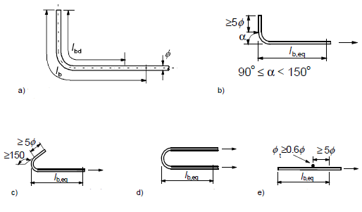
Image 8.1 - Other ways of anchors then straight anchors
a) basic tensile anchor length lb, measured on center line for all shapes
b) equivalent anchor length for standard bend
c) equivalent anchor length for standard hook
d) equivalent anchor length for standard loop
e) equivalent anchor length for bar welded perpendicullar
8.4.2 Limit stress in cohesion
(1)P The ultimate bond stress shall be such that there is an adequate safety margin against bond failure.
(2) The design value of the ultimate bond stress, fbd, for ribbed bars may be taken as:
fbd = 2,25 * η1 * η2 * fctd
where fctd is design value of concrete tensile strength according to 3.1.6(2)P. Due to the increasing brittleness of higher strength concrete, fctk,0,05 should be limited here to the value for C55, unless it can be verified that the average bond strength increases above this limit
η1 coefficient related to the quality of the bond condition and the position of the bar during concreting
(see Figure 8.2):
η1 = 1,0 when ‘good’ conditions are obtained and
η1 = 0,7 for all other cases and for bars in structural elements built with slip-forms, unless it can be shown that ‘good’ bond conditions exist
η2 is related to the bar diameter: η2 = 1,0 for φ ≤ 32 mm η2 = (132 - φ)/100 for φ > 32 mm
Image 8.2 - Description of cohesion conditions
[A] - concreting direction
a) and b) ‘good’ conditions of cohesion for all bars
c) and d) not-hatched area - ‘good’ conditions of cohesion; hatched area - ‘bad’ conditions of cohesion
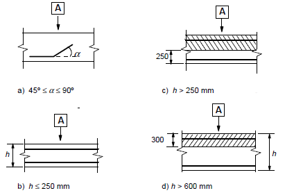
Table 8.2 - Coefficient values fora1, a2, a3, a4, a5
Shape of bars |
Straight
Other than straight
(see Figure 8.1 (b),(c) and (d)) |
α1 = 1,0
α1 = 0,7 if cd>3*ϕ
otherwise α1 = 1,0(see Fig. 8.4 for values of cd) |
α1 = 1,0
α1 = 1,0 |
Concrete cover |
Straight
Other than straight
(see Figure 8.1 (b),(c) and (d)) |
α2 = 1 – 0,15 (cd – φ)/φ; ≥ 0,7; ≤ 1,0
α2 = 1 – 0,15 (cd – 3φ)/φ; ≥ 0,7; ≤ 1,0; (see Fig. 8.4 for values of cd) |
α2 = 1,0
α2 = 1,0 |
Confinement by transverse reinforcement
not welded to main reinforcement |
All types |
α3 = 1 – K*λ; ≥ 0,7; ≤ 1,0 |
α3 = 1,0 |
Confinement by welded transverse reinforcement* |
All types, position and size as specified in Figure 8.1 (e) |
α4 = 0,7 |
α4 = 0,7 |
Confinement by transverse pressure |
All types |
α5 = 1 – 0,04p; ≥ 0,7; ≤ 1,0 |
- |
where: λ = (ΣAst - ΣAst,min)/ As
ΣAst cross-sectional area of the transverse reinforcement along the design anchorage length lbd
ΣAst,min cross-sectional area of the minimum transverse reinforcement = 0,25 As for beams and 0 for slabs
As area of a single anchored bar with maximum bar diameter K values shown in Figure 8.3
p transverse pressure [MPa] at ultimate limit state along lbd
* See also 8.6: For direct supports lbd may be taken less than lb,min provided that there is at least one transverse wire welded within the support. This should be at least 15 mm from the face of the support.